Qashqai J11. Engine control system (HRA2DDT) - part 14


  Index      Nissan     Qashqai J11. Engine control system (HRA2DDT). Service and Repair Manual


Search            copyright infringement  


Content      ..     12      13      14      15     ..


Qashqai J11. Engine control system (HRA2DDT) - part 14


P0325 KNOCK SENSOR (KS)

ECH-209

< DTC/CIRCUIT DIAGNOSIS >

[HRA2DDT]

C

D

E

F

G

H

I

J

K

L

M

A

ECH

N

P

O

NO

>> GO TO 4.

4.

CHECK KNOCK SENSOR POWER SUPPLY CIRCUIT

1.

Disconnect knock sensor harness connector.

2.

Check the continuity between knock sensor harness connector and ECM harness connector.

3.

Also check harness for short to ground.

Is the inspection result normal?

YES

>> GO TO 5.

NO

>> Repair or replace error-detected parts.

5.

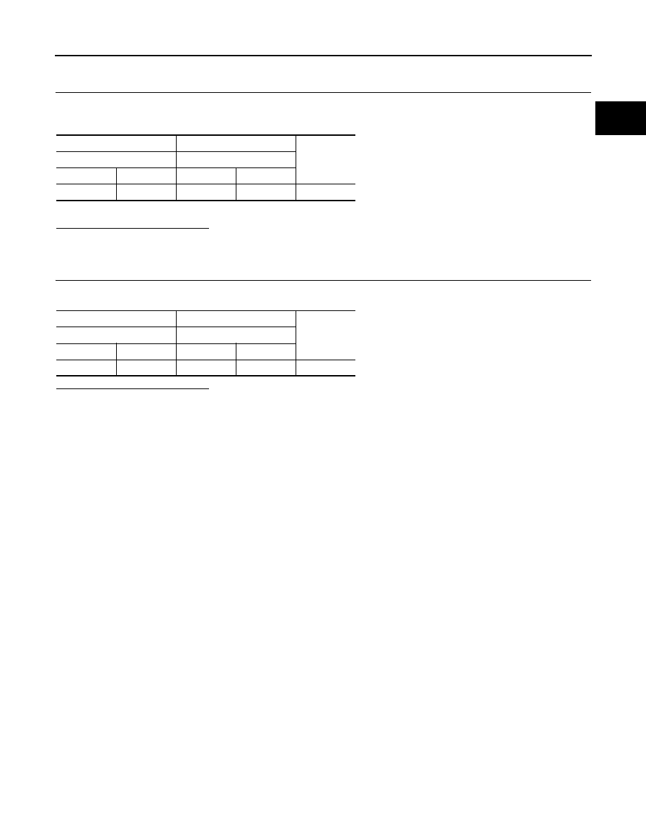
CHECK KNOCK SENSOR GROUND CIRCUIT

Check the continuity between knock sensor harness connector and ECM harness connector.

Is the inspection result normal?

YES

>> Replace knock sensor.

NO

>> Repair or replace error-detected parts.

+

Continuity

Knock sensor

ECM

Connector

Terminal

Connector

Terminal

F33

2

F17

38

Existed

+

Continuity

Knock sensor

ECM

Connector

Terminal

Connector

Terminal

F33

1

F17

42

Existed

ECH-210

< DTC/CIRCUIT DIAGNOSIS >

[HRA2DDT]

P0335 CKP SENSOR (POS)

P0335 CKP SENSOR (POS)

DTC Logic

INFOID:0000000010379102

DTC DETECTION LOGIC

DTC CONFIRMATION PROCEDURE

1.

PRECONDITIONING

Turn ignition switch OFF and wait at least 12 minutes.

>> GO TO 2.

2.

PERFORM DTC CONFIRMATION PROCEDURE

1.

Start the engine and let it idle at least 1 second.

2.

Check DTC.

Is DTC detected?

YES

>> Proceed to 

ECH-210, "Diagnosis Procedure"

.

NO

>> INSPECTION END

Diagnosis Procedure

INFOID:0000000010379103

1.

CHECK CKP SENSOR (POS) HARNESS CONNECTOR CONNECTIONS

1.

Turn ignition switch OFF.

2.

Check crankshaft position (CKP) sensor (POS) harness connector connection.

Is the inspection result normal?

YES

>> GO TO 2.

NO

>> Repair or replace crankshaft position (CKP) sensor (POS) harness connector connection.

2.

CHECK CKP SENSOR (POS) CIRCUIT FOR OPEN AND SHORT

1.

Disconnect ECM harness connector.

2.

Check the continuity CKP sensor (POS) circuit.

3.

Also check harness for short to ground and short to power. 

Is the inspection result normal?

YES

>> GO TO 5.

NO

>> GO TO 3.

3.

CHECK CKP SENSOR (POS) INPUT SIGNAL CIRCUIT FOR OPEN AND SHORT

1.

Disconnect crankshaft position (CKP) sensor (POS) harness connector.

2.

Check the continuity between CKP sensor (POS) harness connector and ECM harness connector.

DTC No.

CONSULT screen terms

(Trouble diagnosis content)

DTC detecting condition

Possible cause

P0335

CRANK POS SEN (OBD) 
[P0335]
(Crankshaft position sensor 
“A” circuit)

• The crankshaft position (CKP) sensor sig-

nal is not detected by the ECM during the 
first few seconds of engine cranking.

• Crankshaft position (CKP) sensor signal 

is not in the normal pattern when engine 
started for 1 second or more.

• ECM cannot detect crankshaft position 

sensor signal when engine started.

• Crankshaft position sensor signal is noisy.

• Harness or connectors

(The sensor circuit is open or shorted.)

• Crankshaft position sensor (POS)
• Signal plate

ECM

Continuity

Connector

Terminal

Terminal

F17

35

37

Existed

P0335 CKP SENSOR (POS)

ECH-211

< DTC/CIRCUIT DIAGNOSIS >

[HRA2DDT]

C

D

E

F

G

H

I

J

K

L

M

A

ECH

N

P

O

3.

Also check harness for short to ground and short to power. 

Is the inspection result normal?

YES

>> GO TO 4.

NO

>> Repair open circuit or short to ground or short to power in harness or connectors.

4.

CHECK CKP SENSOR (POS) GROUND CIRCUIT FOR OPEN AND SHORT

1.

Check the continuity between CKP sensor (POS) harness connector and ECM harness connector.

2.

Also check harness for short to ground and short to power. 

Is the inspection result normal?

YES

>> GO TO 5.

NO

>> Repair open circuit or short to ground or short to power in harness or connectors.

5.

CHECK GEAR TOOTH

Visually check for chipping flywheel gear tooth.

Is the inspection result normal?

YES

>> Replace crankshaft position sensor (POS).

NO

>> Replace signal plate.

CKP sensor (POS)

ECM

Continuity

Connector

Terminal

Connector

Terminal

F8

3

F17

35

Existed

CKP sensor (POS)

ECM

Continuity

Connector

Terminal

Connector

Terminal

F8

2

F17

37

Existed

ECH-212

< DTC/CIRCUIT DIAGNOSIS >

[HRA2DDT]

P0340 CMP SENSOR (PHASE)

P0340 CMP SENSOR (PHASE)

DTC Logic

INFOID:0000000010500336

DTC DETECTION LOGIC

DTC CONFIRMATION PROCEDURE

1.

PRECONDITIONING

Turn ignition switch OFF and wait at least 12 minutes.

>> GO TO 2.

2.

PERFORM DTC CONFIRMATION PROCEDURE

1.

Rev engine from idle to 4,000 rpm.

2.

Check DTC.

Is DTC detected?

YES

>> Proceed to 

ECH-212, "Diagnosis Procedure"

.

NO

>> INSPECTION END

Diagnosis Procedure

INFOID:0000000010500337

1.

CHECK STARTING SYSTEM

Turn ignition switch to START position.
Does the engine turn over? Does the starter motor operate?

YES

>> GO TO 2.

NO

>> Check starting system.

2.

CHECK CAMSHAFT POSITION (CMP) SENSOR POWER SUPPLY

1.

Turn ignition switch OFF.

2.

Disconnect camshaft position (CMP) sensor harness connector.

3.

Turn ignition switch ON.

4.

Check the voltage between CMP sensor harness connector and ground.

Is the inspection result normal?

YES

>> GO TO 4.

NO

>> GO TO 3.

3.

CHECK CAMSHAFT POSITION (CMP) SENSOR POWER SUPPLY CIRCUIT

1.

Turn ignition switch OFF.

2.

Disconnect ECM harness connector.

3.

Check the continuity between CMP sensor harness connector and ECM harness connector.

DTC No.

CONSULT screen terms

(Trouble diagnosis con-

tent)

DTC detecting condition

Possible cause

P0340

CAMSHAFT POSI SEN 
[P0340]
(Camshaft position sen-
sor “A” circuit bank 1)

• The cylinder No. signal is not sent to ECM for 

the first few seconds during engine cranking.

• The cylinder No. signal is not sent to ECM 

during engine running.

• The cylinder No. signal is not in the normal 

pattern during engine running.

• Harness or connectors

(Camshaft position sensor circuit is open 
or shorted)

• Camshaft position sensor
• Camshaft (Intake)

+

Voltage

(Approx.)

CMP sensor

Connector

Terminal

F111

1

Ground

5 V

P0340 CMP SENSOR (PHASE)

ECH-213

< DTC/CIRCUIT DIAGNOSIS >

[HRA2DDT]

C

D

E

F

G

H

I

J

K

L

M

A

ECH

N

P

O

4.

Also check harness for short to power.

Is the inspection result normal?

YES

>> Check intermittent incident. Refer to 

GI-41, "Intermittent Incident"

.

NO

>> Repair or replace error-detected parts.

4.

CHECK CMP SENSOR GROUND CIRCUIT

1.

Turn ignition switch OFF.

2.

Disconnect ECM harness connector.

3.

Check the continuity between CMP sensor harness connector and ECM harness connector.

4.

Also check harness for short to power.

Is the inspection result normal?

YES

>> GO TO 5.

NO

>> Repair or replace error-detected parts.

5.

CHECK CMP SENSOR INPUT SIGNAL CIRCUIT

1.

Disconnect ECM harness connector.

2.

Check the continuity between CMP sensor harness connector and ECM harness connector.

3.

Also check harness for short to ground and to power.

Is the inspection result normal?

YES

>> GO TO 6.

NO

>> Repair or replace error-detected parts.

6.

CHECK CAMSHAFT POSITION SENSOR

Check the camshaft position sensor. Refer to 

ECH-214, "Component Inspection"

.

Is the inspection result normal?

YES

>> GO TO 7.

NO

>> Replace camshaft position sensor.

7.

CHECK CAMSHAFT (INT)

Check the following.
• Accumulation of debris to the signal plate of camshaft rear end
• Chipping signal plate of camshaft rear end
Is the inspection result normal?

YES

>> Check intermittent incident. Refer to 

GI-41, "Intermittent Incident"

.

NO

>> Remove debris and clean the signal plate of camshaft rear end or replace camshaft.

+

Continuity

CMP sensor

ECM

Connector

Terminal

Connector

Terminal

F111

1

F18

133

Existed

+

Continuity

CMP sensor

ECM

Connector

Terminal

Connector

Terminal

F111

2

F18

134

Existed

+

Continuity

CMP sensor

ECM

Connector

Terminal

Connector

Terminal

F111

3

F18

135

Existed

ECH-214

< DTC/CIRCUIT DIAGNOSIS >

[HRA2DDT]

P0340 CMP SENSOR (PHASE)

Component Inspection

INFOID:0000000010500338

1.

CHECK CAMSHAFT POSITION SENSOR-I

1.

Turn ignition switch OFF.

2.

Loosen the fixing bolt of the sensor.

3.

Disconnect camshaft position sensor harness connector.

4.

Remove the sensor.

5.

Visually check the sensor for chipping.

Is the inspection result normal?

YES

>> GO TO 2.

NO

>> Replace camshaft position sensor.

2.

CHECK CAMSHAFT POSITION SENSOR-II

Check the resistance camshaft position sensor terminals as per the following.

Is the inspection result normal?

YES

>> INSPECTION END

NO

>> Replace camshaft position sensor.

PBIA9210J

Camshaft position sensor

Resistance

+

Terminals (Polarity)

1

2

More than 100 k

2

3

More than 200 k

P0351, P0352, P0353, P0354 IGNITION COIL

ECH-215

< DTC/CIRCUIT DIAGNOSIS >

[HRA2DDT]

C

D

E

F

G

H

I

J

K

L

M

A

ECH

N

P

O

P0351, P0352, P0353, P0354 IGNITION COIL

DTC Logic

INFOID:0000000010500388

DTC DETECTION LOGIC

DTC CONFIRMATION PROCEDURE

1.

PRECONDITIONING

Turn ignition switch OFF and wait at least 12 minutes.

>> GO TO 2.

2.

PERFORM DTC CONFIRMATION PROCEDURE

1.

Start the engine and let it idle at least 5 second.

2.

Check DTC.

Is DTC detected?

YES

>> Proceed to 

ECH-215, "Diagnosis Procedure"

.

NO

>> INSPECTION END

Diagnosis Procedure

INFOID:0000000010500389

1.

CHECK IGNITION COIL POWER SUPPLY CIRCUIT-1

1.

Turn ignition switch OFF.

2.

Disconnect condenser harness connector.

3.

Turn ignition switch ON.

4.

Check the voltage between condenser harness connector and ground.

Is the inspection result normal?

YES

>> GO TO 4.

NO

>> GO TO 2.

2.

CHECK IGNITION COIL POWER SUPPLY CIRCUIT-2

1.

Turn ignition switch OFF.

2.

Disconnect IPDM E/R harness connector.

3.

Check the continuity between IPDM E/R harness connector and condenser harness connector.

DTC No.

CONSULT screen terms

(Trouble diagnosis content)

DTC detecting condition

Possible cause

P0351

IGNITION COIL A
(Ignition coil “A” primary/sec-
ondary circuit)

• ECM detects the ignition coil circuit is 

open.

• ECM detects the ignition coil circuit is 

short to ground.

• ECM detects the ignition coil circuit is 

short to power.

• Ignition signal circuit is open or shorted
• Ignition coil

P0352

IGNITION COIL B
(Ignition coil “” primary/second-
ary circuit)

P0353

IGNITION COIL C
(Ignition coil “C” primary/sec-
ondary circuit)

P0354

IGNITION COIL D
(Ignition coil “D” primary/sec-
ondary circuit)

+

-

Voltage

Condenser

Connector

Terminal

F200

1

Ground

Battery voltage

ECH-216

< DTC/CIRCUIT DIAGNOSIS >

[HRA2DDT]

P0351, P0352, P0353, P0354 IGNITION COIL

4.

Also check harness for short to ground and short to power.

Is the inspection result normal?

YES

>> Proceed to 

ECH-123, "Diagnosis Procedure"

.

NO

>> GO TO 3.

3.

DETECT MALFUNCTIONING PART

Check the following.
• Harness for open or short between IPDM E/R and condenser

>> Repair or replace error-detected parts.

4.

CHECK CONDENSER GROUND CIRCUIT FOR OPEN AND SHORT

1.

Turn ignition switch OFF.

2.

Check the continuity between condenser harness connector and ground.

3.

Also check harness for short to power.

Is the inspection result normal?

YES

>> GO TO 5.

NO

>> Repair or replace error-detected parts.

5.

CHECK IGNITION COIL POWER SUPPLY CIRCUIT-4

1.

Reconnect all harness connectors disconnected.

2.

Disconnect ignition coil harness connector.

3.

Turn ignition switch ON.

4.

Check the voltage between ignition coil harness connector and ground.

Is the inspection result normal?

YES

>> GO TO 7.

NO

>> GO TO 6.

6.

DETECT MALFUNCTIONING PART

Check the following.
• Harness for open or short between ignition coil and harness connector

>> Repair or replace error-detected parts.

7.

CHECK IGNITION COIL GROUND CIRCUIT FOR OPEN AND SHORT

1.

Turn ignition switch OFF.

IPDM E/R

Condenser

Continuity

Connector

Terminal

Connector

Terminal

F90

96

F200

1

Existed

+

-

Continuity

Condenser

Connector

Terminal

F200

2

Ground

Existed

+

-

Voltage

Ignition coil

Cylinder

Connector

Terminal

1

F24

3

Ground

Battery voltage

2

F25

3

3

F26

3

4

F27

3

P0351, P0352, P0353, P0354 IGNITION COIL

ECH-217

< DTC/CIRCUIT DIAGNOSIS >

[HRA2DDT]

C

D

E

F

G

H

I

J

K

L

M

A

ECH

N

P

O

2.

Check the continuity between ignition coil harness connector and ground.

3.

Also check harness for short to power.

Is the inspection result normal?

YES

>> GO TO 8.

NO

>> Repair or replace error-detected parts.

8.

CHECK IGNITION COIL OUTPUT SIGNAL CIRCUIT FOR OPEN AND SHORT

1.

Disconnect ECM harness connector.

2.

Check the continuity between ignition coil harness connector and ECM harness connector.

3.

Also check harness for short to ground and short to power.

Is the inspection result normal?

YES

>> GO TO 9.

NO

>> Repair or replace error-detected parts.

9.

CHECK IGNITION COIL WITH POWER TRANSISTOR

Check ignition coil with power transistor. Refer to 

ECH-217, "Component Inspection (Ignition Coil)"

.

Is the inspection result normal?

YES

>> Replace condenser.

NO

>> Repair or replace error-detected parts.

Component Inspection (Ignition Coil)

INFOID:0000000010506429

1.

CHECK IGNITION COIL WITH POWER TRANSISTOR-1

1.

Turn ignition switch OFF.

2.

Disconnect ignition coil harness connector.

3.

Check resistance between ignition coil terminals as follows.

Is the inspection result normal?

YES

>> GO TO 2.

NO

>> Replace malfunctioning ignition coil with power transistor.

+

-

Continuity

Ignition coil

Cylinder

Connector

Terminal

1

F24

2

Ground

Existed

2

F25

2

3

F26

2

4

F27

2

Ignition coil

ECM

Continuity

Cylinder

Connector

Terminal

Connector

Terminal

1

F24

1

F17

72

Existed

2

F25

1

76

3

F26

1

79

4

F27

1

80

Ignition coil

Resistance

+

Terminals

1

2

470 

±

 5 

1

3

2

3

ECH-218

< DTC/CIRCUIT DIAGNOSIS >

[HRA2DDT]

P0351, P0352, P0353, P0354 IGNITION COIL

2.

CHECK IGNITION COIL WITH POWER TRANSISTOR-2

CAUTION:

Perform the following procedure in a place where with no combustible objects and good ventilation.
1.

Turn ignition switch OFF.

2.

Reconnect all harness connectors disconnected.

3.

Remove fuel pump fuse in IPDM E/R to release fuel pressure.
NOTE:
Do not use CONSULT to release fuel pressure, or fuel pressure applies again during the following proce-
dure.

4.

Start engine.

5.

After engine stalls, crank it two or three times to release all fuel pressure.

6.

Turn ignition switch OFF.

7.

Remove all ignition coil harness connectors to avoid the electrical discharge from the ignition coils.

8.

Remove ignition coil and spark plug of the cylinder to be checked.

9.

Crank engine for 5 seconds or more to remove combustion gas in the cylinder.

10. Connect spark plug and harness connector to ignition coil.
11. Fix ignition coil using a rope etc. with gap of 13 - 17 mm (0.52 -

0.66 in) between the edge of the spark plug and grounded metal
portion as shown in the figure.

12. Crank engine for about three seconds, and check whether spark

is generated between the spark plug and the grounded metal
portion.

CAUTION:

• Never place the spark plug and the ignition coil within 50

cm (19.7 in) each other. Be careful not to get an electrical
shock while checking, because the electrical discharge
voltage becomes 20 kV or more.

• It might damage the ignition coil if the gap of more than 17 mm (0.66 in) is made.
NOTE:
When the gap is less than 13 mm (0.52 in), spark might be generated even if the coil is malfunc-
tioning.

Is the inspection result normal?

YES

>> INSPECTION END

NO

>> Replace malfunctioning ignition coil with power transistor.

Spark should be generated.

JMBIA0066GB

P0365 EXHAUST VALVE TIMING CONTROL POSITION SENSOR

ECH-219

< DTC/CIRCUIT DIAGNOSIS >

[HRA2DDT]

C

D

E

F

G

H

I

J

K

L

M

A

ECH

N

P

O

P0365 EXHAUST VALVE TIMING CONTROL POSITION SENSOR

DTC Logic

INFOID:0000000010502881

DTC DETECTION LOGIC

DTC CONFIRMATION PROCEDURE

1.

PRECONDITIONING

Turn ignition switch OFF and wait at least 12 minutes.

>> GO TO 2.

2.

PERFORM DTC CONFIRMATION PROCEDURE

1.

Start the engine and let it idle at least 5 second.

2.

Rev engine from idle to 4,000 rpm.

3.

Check DTC.

Is DTC detected?

YES

>> Proceed to 

ECH-219, "Diagnosis Procedure"

.

NO

>> INSPECTION END

Diagnosis Procedure

INFOID:0000000010502882

1.

CHECK EXHAUST VALVE TIMING CONTROL POSITION SENSOR HARNESS CONNECTOR CONNEC-

TIONS

1.

Turn ignition switch OFF.

2.

Check exhaust valve timing control position sensor harness connector connection.

Is the inspection result normal?

YES

>> GO TO 2.

NO

>> Repair or replace error-detected parts.

2.

CHECK EXHAUST VALVE TIMING CONTROL POSITION SENSOR POWER SUPPLY CIRCUIT-1

1.

Disconnect ECM harness connector.

2.

Turn ignition switch ON.

3.

Check the voltage between ECM harness connector terminals as per the following.

4.

Also check harness for short to ground and short to power. 

Is the inspection result normal?

YES

>> GO TO 3.

NO

>> GO TO 5.

DTC No.

CONSULT screen terms

(Trouble diagnosis content)

DTC detecting condition

Possible cause

P0365

CAMSHAFT POSITION 
SENSOR B B1
(Camshaft position sensor 
“B” circuit bank 1)

• The exhaust valve timing control position 

sensor signal is not detected by the ECM 
during the first few seconds of engine 
cranking.

• The exhaust valve timing control position 

sensor signal is not send to ECM during 
engine running.

• The exhaust valve timing control position 

sensor signal is not in the normal pattern 
during engine running.

• Harness or connectors

(The sensor circuit is open or shorted.)

• Exhaust valve timing control position sensor
• Signal plate

ECM

Voltage

(Approx.)

Connector

+

Terminal

Terminal

F18

121

126

5 V

ECH-220

< DTC/CIRCUIT DIAGNOSIS >

[HRA2DDT]

P0365 EXHAUST VALVE TIMING CONTROL POSITION SENSOR

3.

CHECK EXHAUST VALVE TIMING CONTROL POSITION SENSOR SIGNAL CIRCUIT

1.

Turn ignition switch OFF.

2.

Disconnect exhaust valve timing control position sensor harness connector.

3.

Check the continuity between exhaust valve timing control position sensor harness connector and ECM
harness connector.

4.

Also check harness for short to ground and short to power. 

Is the inspection result normal?

YES

>> GO TO 4.

NO

>> Repair or replace error-detected parts.

4.

CHECK CAMSHAFT (EXT)

Check the following.
• Accumulation of debris to the signal plate of camshaft rear end.
• Chipping signal plate of camshaft rear end.
Is the inspection result normal?

YES

>> Replace exhaust valve timing control position sensor.

NO

>> Remove debris and clean the signal plate of camshaft rear end or replace camshaft.

5.

CHECK EXHAUST VALVE TIMING CONTROL POSITION SENSOR POWER SUPPLY CIRCUIT-2

1.

Turn ignition switch OFF.

2.

Disconnect exhaust valve timing control position sensor harness connector.

3.

Check the continuity between exhaust valve timing control position sensor harness connector and ECM
harness connector.

4.

Also check harness for short to ground and short to power. 

Is the inspection result normal?

YES

>> GO TO 6.

NO

>> Repair or replace error-detected parts.

6.

CHECK EXHAUST VALVE TIMING CONTROL POSITION SENSOR GROUND CIRCUIT

1.

Check the continuity between exhaust valve timing control position sensor harness connector and ECM
harness connector.

2.

Also check harness for short to ground and short to power. 

Is the inspection result normal?

YES

>> Perform the trouble diagnosis for power supply circuit.

NO

>> Repair or replace error-detected parts.

Exhaust valve timing control 

position sensor

ECM

Continuity

Connector

Terminal

Connector

Terminal

F12

3

F18

127

Existed

Exhaust valve timing control 

position sensor

ECM

Continuity

Connector

Terminal

Connector

Terminal

F12

1

F18

121

Existed

Exhaust valve timing control 

position sensor

ECM

Continuity

Connector

Terminal

Connector

Terminal

F12

2

F18

126

Existed

P0420 THREE WAY CATALYST FUNCTION

ECH-221

< DTC/CIRCUIT DIAGNOSIS >

[HRA2DDT]

C

D

E

F

G

H

I

J

K

L

M

A

ECH

N

P

O

P0420 THREE WAY CATALYST FUNCTION

DTC Logic

INFOID:0000000010379105

DTC DETECTION LOGIC

NOTE:
If DTC P0420 is displayed with DTC P0095, P0115, P0130, P0135, P0136, P0141, P0170, P0190, P0200,
P0201, P0202, P0203, P0204, P0300, P0301, P0302, P0303, P0304, P0313, P0335, P0443, P1130, P1131,
P1351, P1352, P1544, P1620, P2031, P2243, P2244, P2626 or P2A06, first perform the trouble diagnosis for
DTC without P0420. Refer to 

ECH-71, "DTC Index"

.

DTC CONFIRMATION PROCEDURE

1.

INSPECTION START

NOTE:
DTC P0420 can not duplicate.

>> Proceed to 

ECH-221, "Diagnosis Procedure"

.

Component Function Check

INFOID:0000000010379106

1.

PERFORM COMPONENT FUNCTION CHECK

Without CONSULT

1.

Start engine and warm it up to the normal operating temperature.

2.

Turn ignition switch OFF and wait at least 12 minutes.

3.

Restart engine and keep the engine speed between 3,500 and 4,000 rpm for at least 1 minute under no
load.

4.

Let engine idle for 1 minute.

5.

Open engine hood.

6.

Check the voltage between ECM harness connector terminals under the following condition.

Is the inspection result normal?

YES

>> INSPECTION END

NO

>> Proceed to 

ECH-221, "Diagnosis Procedure"

.

Diagnosis Procedure

INFOID:0000000010379107

1.

CHECK HEATED OXYGEN SENSOR 2

Refer to 

ECH-179, "Diagnosis Procedure"

.

Is the inspection result normal?

YES

>> GO TO 2.

NO

>> GO TO 3.

2.

PERFORM FLYWHEEL LEARNING

DTC No.

CONSULT screen terms

(Trouble diagnosis con-

tent)

DTC detecting condition

Possible cause

P0420

CATALYST SYSTEM
(Catalyst system efficiency 
below threshold bank 1)

Difference between raw and filtered lambda sen-
sor signals anomaly high when submitted to rich-
ness pulses for 25 seconds.

• Three way catalyst (manifold)
• Thermal ageing
• Absent catalytic converter

ECM

Condition

Voltage (V)

Connector

+

Terminal

Terminal

F18

112

100

Keeping engine speed at 3,000 rpm 
constant under no load

The voltage fluctuation cycle takes more than 5 seconds.
• 1 cycle: 0.6 - 1.0 

 0 - 0.3 

 0.6 - 1.0

ECH-222

< DTC/CIRCUIT DIAGNOSIS >

[HRA2DDT]

P0420 THREE WAY CATALYST FUNCTION

1.

Refer to 

ECH-107, "Work Procedure"

.

2.

Check the engine flywheel target’s learning.

Is “DONE” displayed on CONSULT screen?

YES

>> Check intermittent incident. Refer to 

GI-41, "Intermittent Incident"

.

NO

>> GO TO 3.

3.

REPLACE HEATED OXYGEN SENSOR 2

Replace heated oxygen sensor 2.

>> INSPECTION END

P0443 EVAP CANISTER PURGE VOLUME CONTROL SOLENOID VALVE

ECH-223

< DTC/CIRCUIT DIAGNOSIS >

[HRA2DDT]

C

D

E

F

G

H

I

J

K

L

M

A

ECH

N

P

O

P0443 EVAP CANISTER PURGE VOLUME CONTROL SOLENOID VALVE

DTC Logic

INFOID:0000000010379108

DTC DETECTION LOGIC

DTC CONFIRMATION PROCEDURE

1.

PRECONDITIONING

Turn ignition switch OFF and wait at least 12 minutes.
TESTING CONDITION:
Before performing the following procedure, confirm battery voltage is more than 11 V at idle.

>> GO TO 2.

2.

PERFORM DTC CONFIRMATION PROCEDURE

1.

Turn ignition switch ON and wait at least 5 seconds.

2.

Check DTC.

Is DTC detected?

YES

>> Proceed to 

ECH-223, "Diagnosis Procedure"

.

NO

>> INSPECTION END

Diagnosis Procedure

INFOID:0000000010379109

1.

CHECK ECM HARNESS CONNECTOR CONNECTION

1.

Turn ignition switch OFF. 

2.

Check ECM harness connector connection.

Is the inspection result normal?

YES

>> GO TO 2.

NO

>> Repair or replace error-detected parts.

2.

CHECK EVAP CANISTER PURGE VOLUME CONTROL SOLENOID VALVE HARNESS CONNECTOR

CONNECTION

Check EVAP canister purge volume control solenoid valve harness connector connection.

Is the inspection result normal?

YES

>> GO TO 3.

NO

>> Repair or replace error-detected parts.

3.

CHECK EVAP CANISTER PURGE VOLUME CONTROL SOLENOID VALVE POWER SUPPLY CIRCUIT

1.

Turn ignition switch OFF.

2.

Disconnect EVAP canister purge volume control solenoid valve harness connector.

3.

Turn ignition switch ON.

4.

Check the voltage between EVAP canister purge volume control solenoid valve harness connector and
ground.

DTC No.

CONSULT screen terms

(Trouble diagnosis content)

DTC detecting condition

Possible cause

P0443

CANISTER PURGE VALVE
(Evaporative emission system 
purge control valve circuit)

• ECM detects the EVAP canister purge volume 

control solenoid valve circuit is open.

• ECM detects the EVAP canister purge volume 

control solenoid valve circuit is short to ground.

• ECM detects the EVAP canister purge volume 

control solenoid valve circuit is short to power.

• Harness or connectors

(EVAP canister purge volume con-
trol solenoid valve circuit is open or 
shorted.)

• EVAP canister purge volume control 

solenoid valve

ECH-224

< DTC/CIRCUIT DIAGNOSIS >

[HRA2DDT]

P0443 EVAP CANISTER PURGE VOLUME CONTROL SOLENOID VALVE

Is the inspection result normal?

YES

>> GO TO 4.

NO

>> Perform the trouble diagnosis for power supply circuit.

4.

CHECK EVAP CANISTER PURGE VOLUME CONTROL SOLENOID VALVE CIRCUIT

1.

Turn ignition switch OFF.

2.

Disconnect ECM harness connector.

3.

Check the continuity between EVAP canister purge volume control solenoid valve harness connector and
ECM harness connector.

4.

Also check harness for short to ground and to power.

Is the inspection result normal?

YES

>> GO TO 5.

NO

>> Repair or replace error-detected parts.

5.

CHECK EVAP CANISTER PURGE VOLUME CONTROL SOLENOID VALVE

Check EVAP canister purge volume control solenoid valve. Refer to 

ECH-224, "Component Inspection"

.

Is the inspection result normal?

YES

>> Check intermittent incident. Refer to 

GI-41, "Intermittent Incident"

.

NO

>> Repair or replace error-detected parts.

Component Inspection

INFOID:0000000010379110

1.

CHECK EVAP CANISTER PURGE VOLUME CONTROL SOLENOID VALVE

1.

Turn ignition switch OFF.

2.

Disconnect EVAP canister purge volume control solenoid valve harness connector.

3.

Check the resistance between EVAP canister purge volume control solenoid valve terminals as per the
following conditions.

Is the inspection result normal?

YES

>> INSPECTION END

NO

>> Replace EVAP canister purge volume control solenoid valve.

+

Voltage

EVAP canister purge volume control 

solenoid valve

Connector

Terminal

F183

1

Ground

Battery voltage

+

Continuity

EVAP canister purge vol-

ume control solenoid valve

ECM

Connector

Terminal

Connector

Terminal

F183

2

F17

44

Existed

EVAP canister purge volume 

control solenoid valve

Condition

Resistance

+

Terminal

1

2

Temperature

23

°

C (73

°

F)

26 

±

 4 

40

°

C (

40

°

F)

20 

±

 3 


Content      ..     12      13      14      15     ..