Qashqai J11. Engine control system (R9M) - part 23


  Index      Nissan     Qashqai J11. Engine control system (R9M). Service and Repair Manual


Search            copyright infringement  


Content      ..     21      22      23      24     ..


Qashqai J11. Engine control system (R9M) - part 23


EC9-354

< DTC/CIRCUIT DIAGNOSIS >

[R9M]

P1656 ENGINE RESTART BYPASS RELAY

Is the inspection result normal?

YES

>> Check intermittent incident. Refer to 

GI-41, "Intermittent Incident"

.

NO

>> Replace error-detected parts.

Component Inspection (Engine Restart Bypass Control Relay)

INFOID:0000000010507873

1.

CHECK ENGINE RESTART BYPASS CONTROL RELAY

1.

Turn ignition switch OFF.

2.

Remove engine restart bypass control relay.

3.

Check continuity between engine restart bypass control relay
terminals as per the following condition. 

Is the inspection result normal?

YES

>> INSPECTION END

NO

>> Replace engine restart bypass control relay.

Component Inspection (Engine Restart Bypass Relay)

INFOID:0000000010507874

1.

CHECK ENGINE RESTART BYPASS RELAY-1

1.

Turn ignition switch OFF.

2.

Disconnect battery cable from negative terminal.

3.

Remove engine restart bypass relay. Refer to 

EC9-409, "Exploded View"

.

4.

Check the continuity between engine restart bypass relay termi-
nal and engine restart bypass relay body.

Is the inspection result normal?

YES

>> GO TO 2.

NO

>> Replace engine restart bypass relay. Refer to 

EC9-409, "Removal and Installation"

.

2.

CHECK ENGINE RESTART BYPASS RELAY-2

Check the resistance between engine restart bypass relay terminals
as per the following conditions. 

Is the inspection result normal?

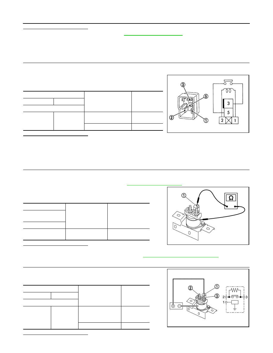
Engine restart bypass control relay

Condition

Continuity

+

Terminal

3

5

12 V direct current supply 
between terminals 1 and 2

Existed

No current supply

Not existed

JSBIA0671ZZ

+

Continuity

Engine restart bypass 

relay

Terminal

1

Engine restart bypass 

relay body

Existed

JSBIA1735ZZ

Engine restart bypass relay

Condition

Resistance

(Approx.)

+

Terminal

2

3

12 V direct current sup-
ply between terminal 1 
and body

10 m

No current supply

JSBIA1736ZZ

P1656 ENGINE RESTART BYPASS RELAY

EC9-355

< DTC/CIRCUIT DIAGNOSIS >

[R9M]

C

D

E

F

G

H

I

J

K

L

M

A

EC9

N

P

O

YES

>> INSPECTION END

NO

>> Replace engine restart bypass relay. Refer to 

EC9-409, "Removal and Installation"

.

EC9-356

< DTC/CIRCUIT DIAGNOSIS >

[R9M]

P1675 ENGINE COOLANT TEMPERATURE

P1675 ENGINE COOLANT TEMPERATURE

DTC Logic

INFOID:0000000010507878

DTC DETECTION LOGIC

If the cooling fan or other component in the cooling system malfunctions, engine coolant temperature will rise.
When the engine coolant temperature reaches an abnormally high temperature condition, a malfunction is
indicated.

CAUTION:

When a malfunction is indicated, be sure to replace the coolant. Also, replace the engine oil. 
1.

Fill radiator with coolant up to specified level with a filling speed of 2 liters per minute. Be sure to
use coolant with the proper mixture ratio.

2.

After refilling coolant, run engine to ensure that no water-flow noise is emitted.

DTC CONFIRMATION PROCEDURE

1.

PERFORM COMPONENT FUNCTION CHECK

Perform component function check. Refer to 

EC9-356, "Component Function Check"

.

NOTE:
Use component function check to check the overall function of the cooling fan. During this check, a DTC might
not be confirmed.

Is the inspection result normal?

YES

>> INSPECTION END

NO

>> Go to 

EC9-357, "Diagnosis Procedure"

.

Component Function Check

INFOID:0000000010507879

1.

PERFORM COMPONENT FUNCTION CHECK-1

WARNING:

Never remove the reservoir tank cap when the engine is hot. Serious burns could be caused by high
pressure fluid escaping from the radiator.
Wrap a thick cloth around cap. Carefully remove the cap by turning it a quarter turn to allow built-up
pressure to escape. Then turn the cap all the way off.
Check the coolant level in the reservoir tank and radiator.
Allow engine to cool before checking coolant level.
Is the coolant level in the reservoir tank and/or radiator below the
proper range?

YES

>> Proceed to 

EC9-357, "Diagnosis Procedure"

.

NO

>> GO TO 2.

2.

PERFORM COMPONENT FUNCTION CHECK-2

DTC No.

CONSULT screen terms

(Trouble diagnosis content)

DTC detecting condition

Possible cause

P1675


(—)

When engine coolant temperature is too high.

• Cooling fan
• Radiator hose
• Radiator
• Radiator  cap
• Water pump
• Thermostat
• Engine coolant bypass 

valve

• Engine coolant temper-

ature sensor

SEF621W

P1675 ENGINE COOLANT TEMPERATURE

EC9-357

< DTC/CIRCUIT DIAGNOSIS >

[R9M]

C

D

E

F

G

H

I

J

K

L

M

A

EC9

N

P

O

Confirm whether customer filled the coolant or not.

Did customer fill the coolant?

YES

>> Proceed to 

EC9-357, "Diagnosis Procedure"

.

NO

>> GO TO 3.

3.

PERFORM COMPONENT FUNCTION CHECK-3

1.

Start engine and let it idle.

2.

Turn air conditioner switch and blower fan switch ON.

3.

Make sure that cooling fan operates at low speed.

Is the inspection result normal?

YES

>> GO TO 4.

NO

>> Proceed to 

EC9-357, "Diagnosis Procedure"

.

4.

PERFORM COMPONENT FUNCTION CHECK-4

1.

Turn ignition switch OFF.

2.

Turn air conditioner switch and blower fan switch OFF.

3.

Disconnect engine coolant temperature sensor harness connector.

4.

Connect 150

 resistor to engine coolant temperature sensor harness connector.

5.

Restart engine and make sure that cooling fan operates at higher speed than low speed.

Is the inspection result normal?

YES

>> INSPECTION END

NO

>> Proceed to 

EC9-357, "Diagnosis Procedure"

.

Diagnosis Procedure

INFOID:0000000010507880

1.

CHECK COOLING FAN OPERATION

Check cooling fan operation.

Is the inspection result normal?

YES

>> GO TO 2.

NO

>> Repair or replace malfunctioning part.

2.

CHECK COOLING SYSTEM FOR LEAK-1

Check cooling system for leak.

Is leakage detected?

YES

>> GO TO 3.

NO

>> GO TO 4.

3.

CHECK COOLING SYSTEM FOR LEAK-2

Check the following for leak.
• Hose
• Radiator
• Radiator cap
• Water pump
• Reservoir tank

>> Repair or replace malfunctioning part.

4.

CHECK RADIATOR CAP

Check radiator cap.

Is the inspection result normal?

YES

>> GO TO 5.

NO

>> Replace radiator cap.

5.

CHECK ENGINE COOLANT BYPASS VALVE

Check engine coolant bypass valve system. Refer to 

EC9-382, "Diagnosis Procedure"

.

Is the inspection result normal?

YES

>> GO TO 6.

EC9-358

< DTC/CIRCUIT DIAGNOSIS >

[R9M]

P1675 ENGINE COOLANT TEMPERATURE

NO

>> Repair or replace error-detected parts.

6.

CHECK THERMOSTAT

Check thermostat.

Is the inspection result normal?

YES

>> GO TO 7.

NO

>> Replace thermostat.

7.

CHECK ENGINE COOLANT TEMPERATURE SENSOR

Check engine coolant temperature sensor routing circuit. Refer to 

EC9-203, "Diagnosis Procedure"

.

Is the inspection result normal?

YES

>> Perform overheating cause analysis. Refer to 

CO-87, "Troubleshooting Chart"

.

NO

>> Replace engine coolant temperature sensor.

P2002 DIESEL PARTICULATE FILTER

EC9-359

< DTC/CIRCUIT DIAGNOSIS >

[R9M]

C

D

E

F

G

H

I

J

K

L

M

A

EC9

N

P

O

P2002 DIESEL PARTICULATE FILTER

DTC Logic

INFOID:0000000010309370

DTC DETECTION LOGIC

NOTE:
If DTC P2002 is displayed with following DTC, perform the trouble diagnosis for following DTC. Refer
to 

EC9-108, "DTC Index"

.

• DTC U0101, U0121, U0415, P0001, P0002, P0045, P0100, P0101, P0102, P0105, P0106, P0115, P0190,

P0200, P0201, P0202, P0203, P0204, P0225, P0226, P0335, P0402, P0470, P0471, P0487, P0488,
P0544, P0560, P060A, P061A, P062B, P0638, P0641, P0651, P0697, P1544, P160C, P160D, P1641,
P1642, P1643, P1650, P2080, P2100, P2119, P2120, P2226, P2263 and P253F.

DTC CONFIRMATION PROCEDURE

1.

PERFORM DIAGNOSIS PROCEDURE

NOTE:
DTC P2002 can not duplicate.

>> Proceed to 

EC9-359, "Diagnosis Procedure"

.

Diagnosis Procedure

INFOID:0000000010309371

1.

CHECK DIESEL PARTICULATE FILTER

Refer to 

EC9-359, "Component Inspection"

.

Is the inspection result normal?

YES

>> GO TO 2.

NO

>> Replace diesel particulate filter.

2.

CHECK INTAKE AIR SYSTEM

Check the intake air system for leakage.

Is the inspection result normal?

YES

>> GO TO 3.

NO

>> Repair or replace error-detected parts and then GO TO 3.

3.

PERFORM SELF-DIAGNOSIS

Perform “Self-diagnostic results” of “ENGINE” using CONSULT.

Is any DTC detected?

YES

>> Replace diesel particulate filter.

NO

>> Perform “SERVICE REGENERATION”. Refer to 

EC9-154, "Work Procedure"

.

Component Inspection

INFOID:0000000010309372

1.

CHECK DIESEL PARTICULATE FILTER

Check diesel particulate filter for damage.

Is the inspection result normal?

DTC No.

CONSULT screen terms

(Trouble diagnosis content)

DTC detecting condition

Possible cause

P2002

PARTICLE FILTER
(Diesel particulate filter efficiency 
below threshold bank 1)
• 1.DEF:CLOGGED
• 2.DEF: COMPONENT IN 

POOR CONDITION

• 3.DEF: OFFSET IMPLAUSI-

BLE

Diesel particulate filter function does not op-
erate properly.

Diesel particulate filter

EC9-360

< DTC/CIRCUIT DIAGNOSIS >

[R9M]

P2002 DIESEL PARTICULATE FILTER

YES

>> Perform “SERVICE REGENERATION”. Refer to 

EC9-154, "Work Procedure"

.

NO

>> Replace diesel particulate filter.

P2080 EGT SENSOR 1

EC9-361

< DTC/CIRCUIT DIAGNOSIS >

[R9M]

C

D

E

F

G

H

I

J

K

L

M

A

EC9

N

P

O

P2080 EGT SENSOR 1

DTC Logic

INFOID:0000000010309375

DTC DETECTION LOGIC

NOTE:
If DTC P2080 is displayed with DTC P0544, first perform the trouble diagnosis for DTC P0544. Refer to

EC9-250, "DTC Logic"

.

DTC CONFIRMATION PROCEDURE

1.

PERFORM DIAGNOSIS PROCEDURE

NOTE:
DTC P2080 can not be duplicate.

>> Proceed to 

EC9-361, "Diagnosis Procedure"

.

Diagnosis Procedure

INFOID:0000000010309376

1.

CHECK INTAKE AIR SYSTEM

1.

Check the air cleaner for clogging.

2.

Check the air duct for connection and cracks.

Is the inspection result normal?

YES

>> GO TO 2.

NO

>> Repair or replace error-detected parts.

2.

CHECK ELECTRIC THROTTLE ACTUATOR

Check the electric throttle actuator. Refer to 

EC9-363, "Component Inspection"

.

Is the inspection result normal?

YES

>> GO TO 3.

NO

>> Replace electric throttle actuator.

3.

CHECK FUEL INJECTOR

Check the fuel injector. Refer to 

EC9-212, "Component Inspection (Fuel Injector)"

.

Is the inspection result normal?

YES

>> GO TO 4.

NO

>> Replace malfunctioning fuel injector.

4.

CHECK EXHAUST SYSTEM

Check the exhaust gas leakage.

Is the inspection result normal?

YES

>> Check intermittent incident. Refer to 

GI-41, "Intermittent Incident"

.

NO

>> Repair or replace error-detected parts.

DTC No.

CONSULT screen terms

(Trouble diagnosis content)

DTC detecting condition

Possible cause

P2080

TBN DOWNS TEMP REG
(Exhaust gas temperature sensor cir-
cuit range/performance bank 1 sen-
sor 1)
• 1.DEF: SIGNAL OUTSIDE UPPER 

LIMIT

• An excessively high voltage from 

exhaust gas temperature sensor 1 is 
sent to ECM.

• Temperature before the turbine is 

more than 810 

°

C (1,490 

°

F)

• Intake air leaks
• Electric throttle actuator
• Fuel injector
• Exhaust gas leaks

EC9-362

< DTC/CIRCUIT DIAGNOSIS >

[R9M]

P2100 THROTTLE CONTROL MOTOR RELAY

P2100 THROTTLE CONTROL MOTOR RELAY

DTC Logic

INFOID:0000000010309377

DTC DETECTION LOGIC

DTC CONFIRMATION PROCEDURE

1.

PRECONDITIONING

If DTC Confirmation Procedure has been previously conducted, always turn ignition switch OFF and wait at
least 1 minute before conducting the next test.

>> GO TO 2.

2.

PERFORM DTC CONFIRMATION PROCEDURE-1

1.

Turn ignition ON at least 2 seconds.

2.

Check DTC.

Is DTC detected?

YES

>> Proceed to 

EC9-362, "Diagnosis Procedure"

.

NO

>> GO TO 3.

3.

PERFORM DTC CONFIRMATION PROCEDURE-2

1.

Start engine and let it idle for at least 2 seconds.

2.

Check DTC.

Is DTC detected?

YES

>> Proceed to 

EC9-362, "Diagnosis Procedure"

.

NO

>> INSPECTION END

Diagnosis Procedure

INFOID:0000000010309378

1.

CHECK ECM HARNESS CONNECTOR CONNECTION

1.

Turn ignition switch OFF.

2.

Check the ECM harness connector connection.

Is the inspection result normal?

YES

>> GO TO 2.

NO

>> Repair or replace error-detected parts.

2.

CHECK ELECTRIC THROTTLE CONTROL ACTUATOR HARNESS CONNECTOR CONNECTION

1.

Turn ignition switch OFF.

2.

Check the electric throttle control actuator harness connector connection.

Is the inspection result normal?

YES

>> GO TO 3.

NO

>> Repair or replace error-detected parts.

3.

CHECK ELECTRIC THROTTLE CONTROL ACTUATOR CIRCUIT

Check the electric throttle control actuator circuit for open and short.

DTC No.

CONSULT screen terms

(Trouble diagnosis content)

DTC detecting condition

Possible cause

P2100

INLET AIR FLAP CIRCUIT
(Throttle actuator “A” control 
motor circuit/open)
• 1.DEF:  —
• 2.DEF: OPERATION 

TEMPERATURE TOO 
HIGH

• ECM detects throttle control motor cir-

cuit is open circuit.

• ECM detects throttle control motor cir-

cuit is short circuit to ground.

• ECM detects throttle control motor cir-

cuit is short circuit to battery.

• Overheating of electric throttle control 

actuator.

• Harness or connectors

(Throttle control motor circuit is open or 
shorted)

• Electric throttle control actuator

P2100 THROTTLE CONTROL MOTOR RELAY

EC9-363

< DTC/CIRCUIT DIAGNOSIS >

[R9M]

C

D

E

F

G

H

I

J

K

L

M

A

EC9

N

P

O

Is the inspection result normal?

YES

>> GO TO 4.

NO

>> Repair or replace error-detected parts.

4.

CHECK THROTTLE CONTROL MOTOR

Perfor

EC9-363, "Component Inspection"

.

Is the inspection result normal?

YES

>> Check intermittent incident. Refer to 

GI-41, "Intermittent Incident"

.

NO

>> Replace electric throttle control actuator.

Component Inspection

INFOID:0000000010309379

1.

CHECK THROTTLE CONTROL MOTOR

1.

Reconnect all harness connectors disconnected.

2.

Check the voltage between ECM harness connectors terminals as per the following conditions.

Is the inspection result normal?

YES

>> INSPECTION END

NO

>> Replace electric throttle control actuator.

+

Continuity

ECM

Electric throttle control actuator

Connector

Terminal

Connector

Terminal

F83

103

F116

2

Existed

107

3

108

1

140

5

152

4

ECM

Condition

Voltage

+

Connector

Terminal

Connector

Terminal

F83

140

E58

29

[Ignition switch: OFF]
For 20 seconds after turn-
ing ignition switch OFF
NOTE:
Repeat several times 
opening and shutting after 
turning ignition switch OFF.

[Ignition switch: OFF]
More than 20 seconds after 
turning ignition switch OFF

0.08 V

152

[Ignition switch: OFF]
For 20 seconds after turn-
ing ignition switch OFF
NOTE:
Repeat several times 
opening and shutting after 
turning ignition switch OFF.

[Ignition switch: OFF]
More than 20 seconds after 
turning ignition switch OFF

1.23 V

JSBIA4823ZZ

JSBIA4828ZZ

EC9-364

< DTC/CIRCUIT DIAGNOSIS >

[R9M]

P2119 ELECTRIC THROTTLE CONTROL FUNCTION

P2119 ELECTRIC THROTTLE CONTROL FUNCTION

DTC Logic

INFOID:0000000010309383

DTC DETECTION LOGIC

Diagnosis Procedure

INFOID:0000000010309384

1.

CHECK INTERMITTENT INCIDENT

Refer to 

GI-41, "Intermittent Incident"

.

Is the inspection result normal?

YES

>> GO TO 2.

NO

>> Repair or replace.

2.

REPLACE ELECTRIC THROTTLE CONTROL ACTUATOR

1.

Replace electric throttle control actuator.

2.

Perform 

EC9-149, "Work Procedure"

.

>> INSPECTION END

DTC No.

CONSULT screen terms

(Trouble diagnosis content)

DTC detecting condition

Possible cause

P2119

AIR INLET FLAP
(Throttle actuator control throt-
tle body range/performance)
• 1.DEF: OFFSET IMPLAUSI-

BLE

ECM detects abnormally closed position of 
throttle control valve.

• Harness or connectors

(Throttle control motor circuit is open 
or shorted)

• Electric throttle control actuator

P2120 APP SENSOR

EC9-365

< DTC/CIRCUIT DIAGNOSIS >

[R9M]

C

D

E

F

G

H

I

J

K

L

M

A

EC9

N

P

O

P2120 APP SENSOR

DTC Logic

INFOID:0000000010309385

DTC DETECTION LOGIC

DTC CONFIRMATION PROCEDURE

1.

PRECONDITIONING

If DTC Confirmation Procedure has been previously conducted, always turn ignition switch OFF and wait at
least 1 minute before conducting the next test.

>> GO TO 2.

2.

PERFORM DTC CONFIRMATION PROCEDURE

1.

Turn ignition switch ON and wait at least 1 second.

2.

Check DTC.

Is DTC detected?

YES

>> Proceed to 

EC9-365, "Diagnosis Procedure"

.

NO

>> INSPECTION END

Diagnosis Procedure

INFOID:0000000010309386

1.

CHECK ACCELERATOR PEDAL POSITION (APP) SENSOR POWER SUPPLY

Check the power supply of the APP sensor.

Is the inspection result normal?

YES

>> GO TO 3.

NO

>> GO TO 2.

2.

CHECK APP SENSOR POWER SUPPLY CIRCUIT

1.

Turn ignition switch OFF.

2.

Check APP sensor circuit for open and short.

Is the inspection result normal?

DTC No.

CONSULT screen terms

(Trouble diagnosis content)

DTC detecting condition

Possible cause

P2120

PEDAL POTENTIOMETER CIR-
CUIT TRACK 2
(Throttle/pedal position sensor/
switch “D” circuit)
• 1.DEF: VOLTAGE TOO LOW
• 2.DEF: VOLTAGE TOO HIGH

• An excessively low voltage from the accel-

erator pedal position (APP) sensor 2 is sent 
to ECM.

• An excessively high voltage from the accel-

erator pedal position (APP) sensor 2 is sent 
to ECM.

• Harness or connectors

(APP sensor 2 circuit is open or 
shorted.)

• APP sensor 2

+

-

Voltage

(Approx.)

APP sensor

Connector

Terminal

E20

4

Ground

5.0 V

5

+

-

Continuity

ECM

APP sensor

Connector

Terminal

Connector

Terminal

E58

23

E20

5

Existed

27

4

EC9-366

< DTC/CIRCUIT DIAGNOSIS >

[R9M]

P2120 APP SENSOR

YES

>> Check ECM power supply circuit. Refer to 

EC9-163, "ECM : Diagnosis Procedure"

.

NO

>> Repair or replace error-detected parts.

3.

CHECK APP CIRCUIT

1.

Turn ignition switch OFF.

2.

Check APP sensor circuit for open and short.

Is the inspection result normal?

YES

>> GO TO 4.

NO

>> Repair or replace error-detected parts.

4.

CHECK APP SENSOR 

Refer to 

EC9-366, "Component Inspection (Accelerator Pedal Position Sensor)"

.

Is the inspection result normal?

YES

>> Check intermittent incident. Refer to 

GI-41, "Intermittent Incident"

.

NO

>> Replace error-detected parts.

Component Inspection (Accelerator Pedal Position Sensor)

INFOID:0000000010309387

1.

CHECK ACCELERATOR PEDAL POSITION SENSOR

1.

Reconnect all harness connectors disconnected.

2.

Turn ignition switch ON.

3.

Check the voltage between ECM harness connector terminals as follows.

Is the inspection result normal?

YES

>> INSPECTION END

NO

>> Replace accelerator pedal assembly.

+

-

Continuity

ECM

APP sensor

Connector

Terminal

Connector

Terminal

E58

21

E20

1

Existed

22

6

30

2

31

3

ECM

Condition

Voltage

Connector

+

-

Terminal

E58

31

30

Accelerator pedal

Fully released

0.6 - 0.9 V

Fully depressed

3.9 - 4.7 V

22

21

Fully released

0.3 - 0.6 V

Fully depressed

1.95 - 2.4 V

P2226 BARO SENSOR

EC9-367

< DTC/CIRCUIT DIAGNOSIS >

[R9M]

C

D

E

F

G

H

I

J

K

L

M

A

EC9

N

P

O

P2226 BARO SENSOR

DTC Logic

INFOID:0000000010309388

DTC DETECTION LOGIC

DTC CONFIRMATION PROCEDURE

1.

PRECONDITIONING

If DTC Confirmation Procedure has been previously conducted, always turn ignition switch OFF and wait at
least 1 minute before conducting the next test.

>> GO TO 2.

2.

PERFORM DTC CONFIRMATION PROCEDURE

1.

Turn ignition switch ON.

2.

Check DTC.

Is DTC detected?

YES

>> Proceed to 

EC9-367, "Diagnosis Procedure"

.

NO

>> INSPECTION END

Diagnosis Procedure

INFOID:0000000010309389

1.

CHECK ECM AIR INLET VISUALLY

Check if foreign matter is blocking the air inlet for ECM.
Is the inspection result normal?

YES

>> Replace ECM. Refer to 

EC9-405, "Removal and Installation"

.

NO

>> Remove foreign matter.

DTC No.

CONSULT screen terms

(Trouble diagnosis content)

DTC detecting condition

Possible cause

P2226

ATMOS PRESS SEN
(Barometric pressure sensor 
“A” circuit)
• 1.DEF: VOLTAGE TOO 

HIGH

• 2.DEF: VOLTAGE TOO 

LOW

• 3.DEF: IMPROPER SIG-

NAL SHAPE

• An excessively low voltage from the atmo-

spheric pressure sensor (built-into ECM) is 
sent to ECM. 

• An excessively high voltage from the atmo-

spheric pressure sensor (built-into ECM) is 
sent to ECM. 

ECM

EC9-368

< DTC/CIRCUIT DIAGNOSIS >

[R9M]

P2243 A/F SENSOR

P2243 A/F SENSOR

DTC Logic

INFOID:0000000010309390

DTC DETECTION LOGIC

DTC CONFIRMATION PROCEDURE

1.

PERFORM DIAGNOSIS PROCEDURE

NOTE:
DTC P2243 can not duplicate. 

>> Proceed to 

EC9-368, "Diagnosis Procedure"

.

Diagnosis Procedure

INFOID:0000000010309391

1.

CHECK ECM HARNESS CONNECTOR CONNECTIONS

1.

Turn ignition switch OFF.

2.

Check ECM harness connector connection.

Is the inspection result normal?

YES

>> GO TO 2.

NO

>> Repair or replace error-detected parts.

2.

CHECK AIR FUEL RATIO (A/F) SENSOR HARNESS CONNECTOR CONNECTIONS

Check A/F sensor harness connector connection.

Is the inspection result normal?

YES

>> GO TO 3.

NO

>> Repair or replace error-detected parts.

3.

CHECK A/F SENSOR CIRCUIT FOR OPEN AND SHORT

Check A/F sensor circuit for open and short.

Is the inspection result normal?

YES

>> GO TO 4.

NO

>> Repair or replace error-detected parts.

4.

CHECK INTERMITTENT INCIDENT

Perform 

GI-41, "Intermittent Incident"

.

Is the inspection result normal?

YES

>> GO TO 5.

DTC No.

CONSULT screen terms

(Trouble diagnosis content)

DTC detecting condition

Possible cause

P2243

PROPOR RICH SEN CIRC
(O2 sensor reference volt-
age circuit/open bank 1 sen-
sor 1)
• CO: OPEN CIRCUIT

ECM detects air fuel ratio (A/F) sensor circuit is 
open circuit.

• Harness or connectors

(A/F sensor circuit is open.)

• A/F sensor 

+

-

Continuity

ECM

A/F sensor

Connector

Terminal

Connector

Terminal

F82

89

F75

3

Existed

F83

115

6

116

2

119

1

P2243 A/F SENSOR

EC9-369

< DTC/CIRCUIT DIAGNOSIS >

[R9M]

C

D

E

F

G

H

I

J

K

L

M

A

EC9

N

P

O

NO

>> Repair or replace error-detected parts.

5.

REPLACE A/F SENSOR

Replace A/F sensor.

CAUTION:

• Discard any A/F sensor which has been dropped from a height of more than 0.5 m (19.7 in) onto a

hard surface such as a concrete floor; use a new one.

• Before installing new A/F sensor, clean exhaust system threads using Heated Oxygen Sensor

Thread Cleaner tool and approved anti-seize lubricant.

>> INSPECTION END


Content      ..     21      22      23      24     ..