Qashqai J11. Brake system - part 6
BR-82
< REMOVAL AND INSTALLATION >
[RHD]
FRONT DISC BRAKE
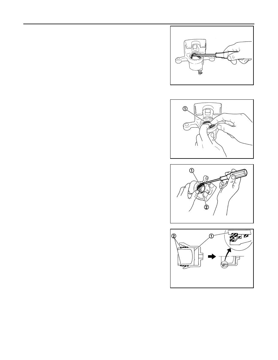
5.
Remove piston seal from cylinder body using suitable tool.
CAUTION:
Be careful not to damage a cylinder inner wall.
ASSEMBLY
1.
Apply rubber grease to piston seal (1), and install to cylinder
body.
CAUTION:
Never reuse piston seal.
2.
Apply rubber grease to piston boot (1). Cover the piston (2) end
with piston boot, and then install cylinder side lip on piston boot
securely into a groove on cylinder body.
CAUTION:
Never reuse piston boot.
3.
Apply brake fluid to piston (1). Push piston into cylinder body by
hand and push piston boot (2) piston-side lip into the piston
groove.
CAUTION:
Press the piston evenly and vary the pressing point to pre-
vent cylinder inner wall from being rubbed.
4.
Apply rubber grease to bushing, install bushing to sliding pin.
5.
Apply rubber grease to sliding pins and sliding pin boots, install
sliding pins and sliding pin boots to torque member.
6.
Install the cylinder body to the torque member and tighten the
sliding pin bolts to the specified torque.
BRAKE CALIPER ASSEMBLY : Inspection and Adjustment
INFOID:0000000010305482
INSPECTION AFTER DISASSEMBLY
Cylinder Body
Check the inner wall of the cylinder for rust, wear, cracks or damage. Replace the cylinder if any abnormal
condition is detected.
CAUTION:
Always clean with new brake fluid. Never clean with mineral oil such as gasoline and light oil.
JPFIA0038ZZ
JPFIA0039ZZ
JPFIA0040ZZ
JPFIA0034ZZ