Qashqai J11. Brake system - part 4


  Index      Nissan     Qashqai J11. Brake system. Service and Repair Manual


Search            copyright infringement  


Content      ..     2      3      4      5     ..


Qashqai J11. Brake system - part 4


BR-50

< PRECAUTION >

[RHD]

PRECAUTIONS

Precaution for Procedure without Cowl Top Cover

INFOID:0000000010305431

When performing the procedure after removing cowl top cover, cover
the lower end of windshield with urethane, etc.

Precaution for Brake System

INFOID:0000000010305432

WARNING:

Clean any dust from the front brake and rear brake with a vacuum dust collector. Never blow with com-
pressed air.

CAUTION:

• Only use “DOT 4” brake fluid. Refer to 

MA-59, "Fluids and Lubricants"

.

• Never reuse drained brake fluid.
• Never spill or splash brake fluid on painted surfaces. Brake fluid may seriously damage paint. Wipe it

off immediately and wash with water if it gets on a painted surface.

• Always clean with new brake fluid when cleaning the master cylinder, brake caliper and other com-

ponents.

• Never use mineral oils such as gasoline or light oil to clean. They may damage rubber parts and

cause improper operation.

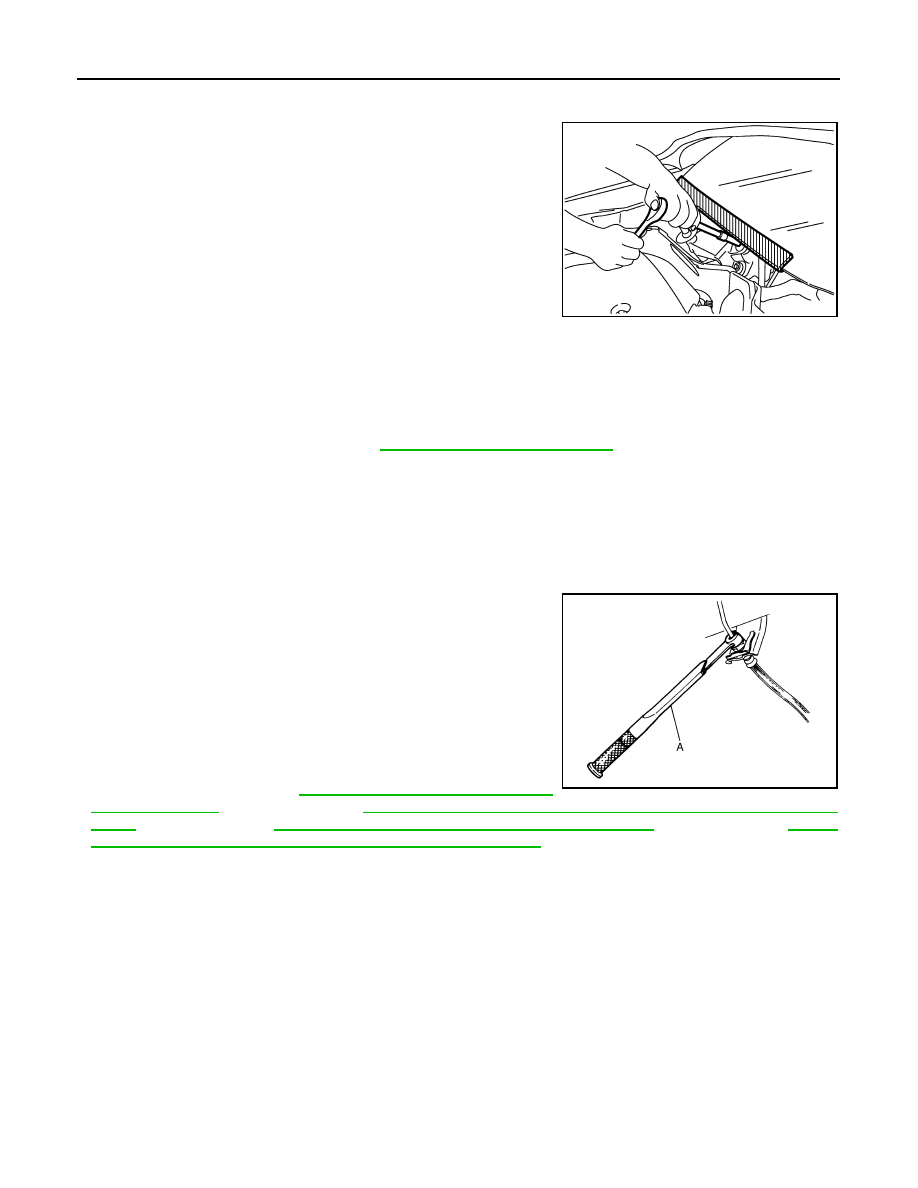
• Always loosen the brake tube flare nut with a flare nut wrench.
• Tighten the brake tube flare nut to the specified torque with

flare nut torque wrench (A).

• Always confirm the specified tightening torque when install-

ing the brake pipes.

• Turn the ignition switch OFF and disconnect the ABS actuator

and electric unit (control unit) connector or the battery nega-
tive terminal before performing the work.

• Check that no brake fluid leakage is present after replacing

the parts.

• Burnish the brake contact surfaces after refinishing or replac-

ing rotors, after replacing pads, or if a soft pedal occurs at
very low mileage. Refer to 

BR-79, "BRAKE PAD : Inspection

and Adjustment"

 (front brake pad), 

BR-82, "BRAKE CALIPER ASSEMBLY : Inspection and Adjust-

ment"

 (front disc rotor), 

BR-85, "BRAKE PAD : Inspection and Adjustment"

 (rear brake pad), 

BR-89,

"BRAKE CALIPER ASSEMBLY : Inspection and Adjustment"

 (rear disc rotor).

PIIB3706J

JPFIA0061ZZ

PREPARATION

BR-51

< PREPARATION >

[RHD]

C

D

E

G

H

I

J

K

L

M

A

B

BR

N

O

P

PREPARATION

PREPARATION

Commercial Service Tool

INFOID:0000000010305433

Tool name

Description

Pin punch
a: 4 mm (0.16 in) dia.

Removing and installing reservoir tank 
pin

NT410

BR-52

< PERIODIC MAINTENANCE >

[RHD]

BRAKE PEDAL

PERIODIC MAINTENANCE

BRAKE PEDAL

Inspection and Adjustment

INFOID:0000000010305434

INSPECTION

Brake Pedal Height

Check the height (H

1

) between the accelerator pedal stopper (1) and

the brake pedal upper surface.

CAUTION:

Remove the floor trim.

ASCD brake Switch and Stop Lamp Switch

Check the clearance (C) between bracket (1) and ASCD brake
switch/stop lamp switch (2) threaded end.

CAUTION:

The stop lamp must be turned off when the brake pedal is
released.
NOTE:
Pull the brake pedal pad to make the clearance between bracket and ASCD brake switch/stop lamp switch
threaded end.

Brake Pedal Play

Press the brake pedal. Check the brake pedal play (A).

Depressed Brake Pedal Height

Standard

Brake pedal height (H

1

)

: Refer to 

BR-90, "Brake 

Pedal"

.

JPFIA0119ZZ

Standard

Clearance (C) between 
bracket and ASCD brake 
switch/stop lamp switch 
threaded end

: Refer to 

BR-90, "Brake 

Pedal"

.

JPFIA0206ZZ

Standard

Pedal play (A)

: Refer to 

BR-90, "Brake 

Pedal"

.

JPFIA0121ZZ

BRAKE PEDAL

BR-53

< PERIODIC MAINTENANCE >

[RHD]

C

D

E

G

H

I

J

K

L

M

A

B

BR

N

O

P

Check the height between the accelerator pedal stopper (1) and the
brake pedal upper surface (H

2

) when depressing the brake pedal at

490 N (50 kg, 110 lb) while turning engine ON.

CAUTION:

Remove the floor trim.

ADJUSTMENT

Brake Pedal Height

1.

Disconnect the harness connector from ASCD brake switch and stop lamp switch.

2.

Turn the ASCD brake switch and stop lamp switch 45

°

 counterclockwise.

3.

Loosen the input rod lock nut (1). Adjust the brake pedal to the
specification. Tighten the input rod lock nut to the specification.
Refer to 

BR-72, "Exploded View"

.

CAUTION:

The threaded end of the input rod (2) must project to the
inner side (L) of the clevis (3).

ASCD brake Switch and Stop Lamp Switch

1.

Disconnect the harness connector from ASCD brake switch and stop lamp switch.

2.

Turn the ASCD brake switch and stop lamp switch 45

°

 counterclockwise.

3.

Press-fit ASCD brake switch/stop lamp switch (2) until ASCD
brake switch/stop lamp switch hits the bracket (1) 45

°

 clockwise.

CAUTION:

• The clearance (C) between the bracket and ASCD brake

switch/stop lamp switch threaded end must be the speci-
fied value. Refer to 

BR-90, "Brake Pedal"

• The stop lamp must be turned off when the brake pedal is

released.

Brake Pedal Play

1.

Disconnect the harness connector from ASCD brake switch and stop lamp switch.

2.

Turn the ASCD brake switch and stop lamp switch 45

°

 counterclockwise.

Standard

Depressed brake pedal 
height (H

2

)

: Refer to 

BR-90, "Brake 

Pedal"

.

JPFIA0120ZZ

JPFIA0003ZZ

Standard

Brake pedal height (H

1

)

: Refer to 

BR-90, "Brake 

Pedal"

.

JPFIA0119ZZ

JPFIA0206ZZ

BR-54

< PERIODIC MAINTENANCE >

[RHD]

BRAKE PEDAL

3.

Press-fit ASCD brake switch/stop lamp switch (2) until ASCD
brake switch/stop lamp switch hits the bracket (1) 45

°

 clockwise.

CAUTION:

• The clearance (C) between the bracket and ASCD brake

switch/stop lamp switch threaded end must be the speci-
fied value. Refer to 

BR-90, "Brake Pedal"

• The stop lamp must be turned off when the brake pedal is

released.

JPFIA0206ZZ

BRAKE FLUID

BR-55

< PERIODIC MAINTENANCE >

[RHD]

C

D

E

G

H

I

J

K

L

M

A

B

BR

N

O

P

BRAKE FLUID

Inspection

INFOID:0000000010305435

BRAKE FLUID LEVEL

• Check that the fluid level in the reservoir tank is within the specified

range (MAX – MIN lines).

• Visually check for any brake fluid leakage around the reservoir

tank.

• Check the brake system for any leakage if the fluid level is

extremely low (lower than MIN).

• Check the brake system for fluid leakage if the warning lamp

remains illuminated even after the parking brake is released.

BRAKE LINE

1.

Check brake line (tubes and hoses) for cracks, deterioration or other damage. Replace any damaged
parts.

2.

Check for fluid leakage by fully depressing brake pedal while
engine is running.

CAUTION:

If leakage occurs around joints, retighten or, if necessary,
replace damaged parts.

Draining

INFOID:0000000010305436

CAUTION:

• Never spill or splash brake fluid on painted surfaces. Brake fluid may seriously damage paint. Wipe it

off immediately and wash with water if it gets on a painted surface.

• Turn the ignition switch OFF and disconnect the ABS actuator and electric unit (control unit) con-

nector or the battery negative terminal before draining.

1.

Connect a vinyl tube to the bleed valve.

2.

Depress the brake pedal and loosen the bleeder valve to gradu-
ally discharge brake fluid.

Refilling

INFOID:0000000010305437

CAUTION:

Turn the ignition switch OFF and disconnect the ABS actuator and electric unit (control unit) connec-
tor or the battery negative terminal before refilling.

JPFIA0007ZZ

SBR389C

BRA0007D

BR-56

< PERIODIC MAINTENANCE >

[RHD]

BRAKE FLUID

1.

Check that there is no foreign material in the reservoir tank, and
refill with new brake fluid.

CAUTION:

Never reuse drained brake fluid.

2.

Loosen the bleeder valve, slowly depress the brake pedal to the
full stroke, and then release the pedal. Repeat this operation at
intervals of 2 or 3 seconds until all brake fluid is discharged.
Then close the bleeder valve with the brake pedal depressed.
Repeat the same work on each wheel.

3.

Perform the air bleeding. Refer to 

BR-56, "Bleeding Brake Sys-

tem"

.

Bleeding Brake System

INFOID:0000000010305438

CAUTION:

• Turn the ignition switch OFF and disconnect the ABS actuator and electric unit (control unit) con-

nector or the battery negative terminal before performing the work.

• Monitor the fluid level in the reservoir tank during the air bleeding. 
• Always use new brake fluid for refilling. Never reuse the drained brake fluid.

1.

Connect a vinyl tube to the bleeder valve of the rear left brake.

2.

Fully depress the brake pedal 4 to 5 times.

3.

Loosen the bleeder valve and bleed air with the brake pedal depressed, and then quickly tighten the
bleeder valve.

4.

Repeat steps 2 and 3 until all of the air is out of the brake line.
In case of EPB rear caliper, operate parkink brake 5 times to bleed the air.

5.

Tighten the bleeder valve to the specified torque. Refer to 

BR-80, "BRAKE CALIPER ASSEMBLY :

Exploded View"

 (front disc brake), 

BR-86, "BRAKE CALIPER ASSEMBLY : Exploded View"

 (rear disc

brake).

6.

Perform steps 1 to 5 for the rear left brake 

front right brake 

 rear right brake 

 and front left brake in

order.

7.

Check that the fluid level in the reservoir tank is within the specified range after air bleeding. Refer to 

BR-

55, "Inspection"

.

PFIA0403J

BRAKE MASTER CYLINDER

BR-57

< PERIODIC MAINTENANCE >

[RHD]

C

D

E

G

H

I

J

K

L

M

A

B

BR

N

O

P

BRAKE MASTER CYLINDER

Inspection

INFOID:0000000010305439

FLUID LEAK

Check for brake fluid leakage from the master cylinder mounting face, reservoir tank mounting face and brake
tube connections.

BR-58

< PERIODIC MAINTENANCE >

[RHD]

BRAKE BOOSTER

BRAKE BOOSTER

Inspection

INFOID:0000000010305440

OPERATION

Depress the brake pedal several times at 5-second intervals with the
engine stopped. Start the engine with the brake pedal fully
depressed. Check that the clearance between brake pedal and dash
lower panel decreases.
NOTE:
A slight impact with a small click may be felt on the pedal when the
brake pedal is fully depressed. This is a normal phenomenon due to
the brake system operation.

AIR TIGHT

• Idle the engine for 1 minute to apply vacuum to the brake booster,

and stop the engine. Then depress the brake pedal several times
at 5-second intervals until the accumulated vacuum is released to
atmospheric pressure. Check that the clearance between brake
pedal and dash lower panel gradually increases (A 

 B 

 C) each

time the brake pedal is depressed during this operation.

• Depress the brake pedal with the engine running. Then stop the

engine while holding down the brake pedal. Check that the brake
pedal stroke does not change after holding down the brake pedal
for 30 seconds or more.
NOTE:
A slight impact with a small click may be felt on the pedal when the
brake pedal is fully depressed. This is a normal phenomenon due
to the brake system operation.

BRA0037D

JPFIA0043ZZ

JPFIA0044ZZ

FRONT DISC BRAKE

BR-59

< PERIODIC MAINTENANCE >

[RHD]

C

D

E

G

H

I

J

K

L

M

A

B

BR

N

O

P

FRONT DISC BRAKE

BRAKE PAD

BRAKE PAD : Inspection

INFOID:0000000010305441

PAD WEAR

Check pad thickness from an inspection hole on cylinder body.
Check using a scale if necessary. 

DISC ROTOR

DISC ROTOR : Inspection

INFOID:0000000010305442

APPEARANCE

Check surface of disc rotor for uneven wear, cracks, and serious damage. Replace if there are.

RUNOUT

1.

Fix the disc rotor to the wheel hub and bearing assembly with
wheel nuts (2 points at least).

2.

Inspect the runout with a dial gauge. [Measured at 10 mm (0.39
in) inside the disc edge.] 

NOTE:
Check the wheel bearing axial end play before the inspection.
Refer to 

FAX-8, "Inspection"

 (2WD), 

FAX-47, "Inspection"

(4WD).   

3.

Find the installation position with a minimum runout by shifting the disc rotor-to-wheel hub and bearing
assembly installation position by one hole at a time if the runout exceeds the limit value.

4.

Replace or lathe the disc rotor if the runout exceeds the limit even after the above operation.

THICKNESS

Check the thickness of the disc rotor using a micrometer. Replace
the disc rotor if the thickness is below the wear limit. 

Standard thickness

: Refer to 

BR-90, "Front 

Disc Brake"

.

Wear limit thickness

: Refer to 

BR-90, "Front 

Disc Brake"

.

BRA0010D

Runout limit

: Refer to 

BR-90, "Front 

Disc Brake"

.

SBR019B

Wear limit thickness

: Refer to 

BR-90, "Front 

Disc Brake"

.

SBR020B

BR-60

< PERIODIC MAINTENANCE >

[RHD]

REAR DISC BRAKE

REAR DISC BRAKE

BRAKE PAD

BRAKE PAD : Inspection

INFOID:0000000010305443

PAD WEAR

Check pad thickness from an inspection hole on cylinder body.
Check using a scale if necessary.

DISC ROTOR

DISC ROTOR : Inspection

INFOID:0000000010305444

APPEARANCE

Check surface of disc rotor for uneven wear, cracks, and serious damage. Replace if there are.

RUNOUT

1.

Fix the disc rotor to the wheel hub and bearing assembly with
wheel nuts (2 points at least).

2.

Inspect the runout with a dial gauge. [Measured at 10 mm (0.39
in) inside disc edge.]

NOTE:
Check the wheel bearing axial end play before the inspection.
Refer to 

RAX-3, "Inspection"

 (2WD), 

RAX-10, "Inspection"

(4WD).

3.

Find the installation position with a minimum runout by shifting the disc rotor-to-wheel hub and bearing
assembly installation position by one hole at a time if the runout exceeds the limit value.

4.

Replace or lathe the disc rotor if the runout exceeds the limit even after the above operation.

THICKNESS

Check the thickness of the disc rotor using a micrometer. Replace
the disc rotor if the thickness is below the wear limit.

Standard thickness

: Refer to 

BR-90, "Rear 

Disc Brake"

.

Wear limit thickness

: Refer to 

BR-90, "Rear 

Disc Brake"

.

BRA0010D

Runout limit

: Refer to 

BR-90, "Rear 

Disc Brake"

.

BRA0697D

Wear limit thickness

: Refer to 

BR-90, "Rear 

Disc Brake"

.

SFIA2284E

BRAKE PEDAL

BR-61

< REMOVAL AND INSTALLATION >

[RHD]

C

D

E

G

H

I

J

K

L

M

A

B

BR

N

O

P

REMOVAL AND INSTALLATION

BRAKE PEDAL

Exploded View

INFOID:0000000010305445

*

AT model

Removal and Installation

INFOID:0000000010471511

REMOVAL

1.

Remove instrument lower panel LH. Refer to 

IP-13, "Removal and Installation"

.

2.

Remove the knee protector. Refer to 

IP-12, "Exploded View"

.

3.

Remove snap pin and clevis pin from clevis of brake booster.

4.

Disconnect the harness connectors from the stop lamp switch and brake pedal position switch.

5.

Remove the accelerator pedal. Refer to 

ACC-3, "Removal and Installation"

.

6.

Remove the brake pedal

CAUTION:

Support the brake booster and master cylinder to prevent contact with other components.

INSTALLATION

Note the following, and installation is the reverse order of removal.
• Apply the multi-purpose grease to the clevis pin and the mating faces. (Not necessary if grease has been

already applied.)

NOTE:
The clevis pin may be inserted in either direction.

1.

Clevis pin

2.

Brake pedal assembly

3.

Stop lamp switch

4.

ASCD brake switch (shift lock brqke 
switch*)

5.

Clip

6.

Snap pin

: Apply multi-purpose grease.

Refer to 

GI-4, "Components"

 for symbols not described on the above.

E1FIA0147GB

BR-62

< REMOVAL AND INSTALLATION >

[RHD]

BRAKE PEDAL

Inspection and Adjustment

INFOID:0000000010305447

INSPECTION AFTER REMOVAL

• Check the following items and replace the brake pedal assembly if necessary.
- Check the brake pedal upper rivet for deformation.
- Check the brake pedal for bend, damage, and cracks on the welded parts.

• Check clevis pin and plastic stopper (A) for damage and deforma-

tion. If any is found, replace clevis pin.

ADJUSTMENT AFTER INSTALLATION

• Perform the brake pedal adjustment after installing the brake pedal assembly. Refer to 

BR-52, "Inspection

and Adjustment"

.

• Perform the accelerator pedal check after installing the accelerator pedal. Refer to 

ACC-3, "Inspection"

.

PFIA0756J

BRAKE PIPING

BR-63

< REMOVAL AND INSTALLATION >

[RHD]

C

D

E

G

H

I

J

K

L

M

A

B

BR

N

O

P

BRAKE PIPING

FRONT

FRONT : Exploded View

INFOID:0000000010305452

1.

Brake tube

2.

Brake booster

3.

Master cylinder assembly

4.

Connector

5.

ABS actuator and electric unit (con-
trol unit)

6.

Lock plate

7.

Brake hose

8.

Union bolt

A.

To front brake hose

B.

To rear brake tube

Refer to 

GI-4, "Components"

 for symbols in the figure.

E1FIA0149GB

BR-64

< REMOVAL AND INSTALLATION >

[RHD]

BRAKE PIPING

FRONT : Hydraulic Piping

INFOID:0000000010305453

FRONT : Removal and Installation

INFOID:0000000010305454

REMOVAL

CAUTION:

Never spill or splash brake fluid on painted surfaces. Brake fluid may seriously damage paint. Wipe it
off immediately and wash with water if it gets on a painted surface.
1.

Remove tires.

2.

Drain brake fluid. Refer to 

BR-55, "Draining"

.

3.

Loosen the flare nut with a flare nut wrench and separate the brake tube from the hose.

CAUTION:

• Never scratch the flare nut and the brake tube.
• Never bend sharply, twist or strongly pull out the brake hoses and tubes.
• Cover open end of brake tubes and hoses when disconnecting to prevent entrance of dirt.

4.

Remove the union bolt and remove the brake hose from the brake caliper assembly.

5.

Remove the lock plate and remove the brake hose.

INSTALLATION

CAUTION:

Never spill or splash brake fluid on painted surfaces. Brake fluid may seriously damage paint. Wipe it
off immediately and wash with water if it gets on a painted surface.
1.

Assemble the union bolt and the copper washer to the brake hose.

CAUTION:

Never reuse the copper washer.

1.

Brake booster

2.

Master cylinder assembly

3.

Front disc brake

4.

ABS actuator and electric unit (con-
trol unit)

5.

Connector

6.

Rear disc brake

A.

Brake tube

B.

Brake hose

 : Flare nut

 : Union bolt

 : Connector

JPFIA0079ZZ

BRAKE PIPING

BR-65

< REMOVAL AND INSTALLATION >

[RHD]

C

D

E

G

H

I

J

K

L

M

A

B

BR

N

O

P

2.

Align the brake hose pin to the projection (A) of the brake caliper
assembly and tighten the union bolt (1) to the specified torque.

3.

Install the brake tube to the brake hose, temporarily tighten the
flare nut by hand until it does not rotate further, and fix the brake
hose to the bracket with the lock plate.

CAUTION:

Check that all brake hoses and tubes are not twisted and
bent.

4.

Tighten the flare nut to the specified torque with a flare nut
torque wrench.

CAUTION:

Never scratch the flare nut and the brake tube.

5.

Refill with new brake fluid and perform the air bleeding. Refer to 

BR-56, "Bleeding Brake System"

.

CAUTION:

Never reuse drained brake fluid.

6.

Install tires.

FRONT : Inspection

INFOID:0000000010305455

INSPECTION AFTER INSTALLATOIN

1.

Check the brake hoses and tubes for the following: no scratches; no twist and deformation; no interfer-
ence with other components when steering the steering wheel; no looseness at connections.

2.

Depress the brake pedal with a force of 785 N (80 kg, 176 lb) and hold down the pedal for approximately
5 seconds with the engine running. Check for any fluid leakage.

CAUTION:

Retighten the applicable connection to the specified torque and repair any abnormal (damaged,
worn or deformed) part if any brake fluid leakage is present.

REAR

REAR : Exploded View

INFOID:0000000010305456

JPFIA0099ZZ

JPFIA0077GB


Content      ..     2      3      4      5     ..