Qashqai J11. Audio, Visual & Navigation System - part 5
AV
COMPONENT PARTS
AV-65
< SYSTEM DESCRIPTION >
[DISPLAY AUDIO]
C
D
E
F
G
H
I
J
K
L
M
B
A
O
P
SYSTEM DESCRIPTION
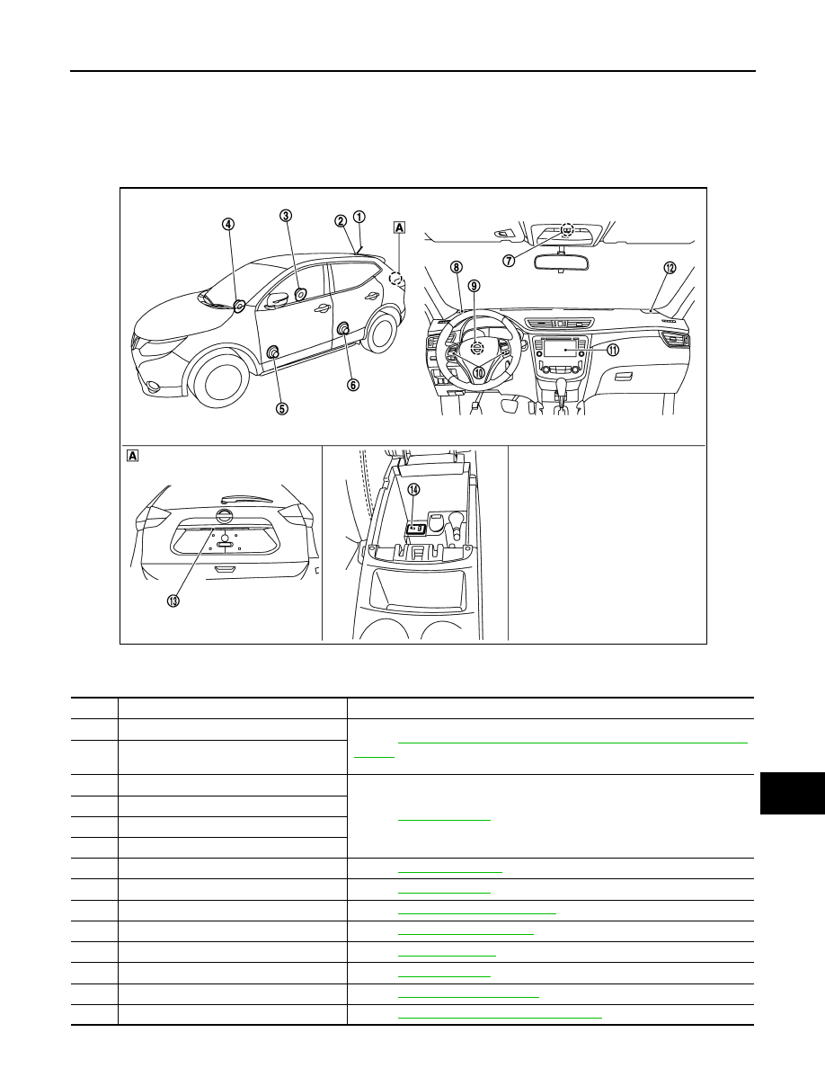
COMPONENT PARTS
Component Parts Location
INFOID:0000000010435593
A. Center of back door
E1NIA0075ZZ
No.
Component
Function
1.
Rod antenna
Refer to
AV-68, "Rod Antenna, Antenna Amp., Satellite Antenna and Antenna
.
2.
Antenna base (antenna amp. and satellite
antenna)
3.
Rear door speaker RH
Refer to
.
4.
Front door speaker RH
5.
Front door speaker LH
6.
Rear door speaker LH
7.
Microphone
.
8.
Front tweeter LH
.
9.
Steering angle sensor
Refer to
AV-68, "Steering Angle Sensor"
.
10.
Steering switches
Refer to
.
11.
Audio unit
Refer to
12.
Front tweeter RH
.
13.
Rear view camera
Refer to
.
14.
USB interface and AUX in jack
Refer to