Nissan Qashqai J11. Manual - part 904
BR-88
< REMOVAL AND INSTALLATION >
[RHD]
REAR DISC BRAKE
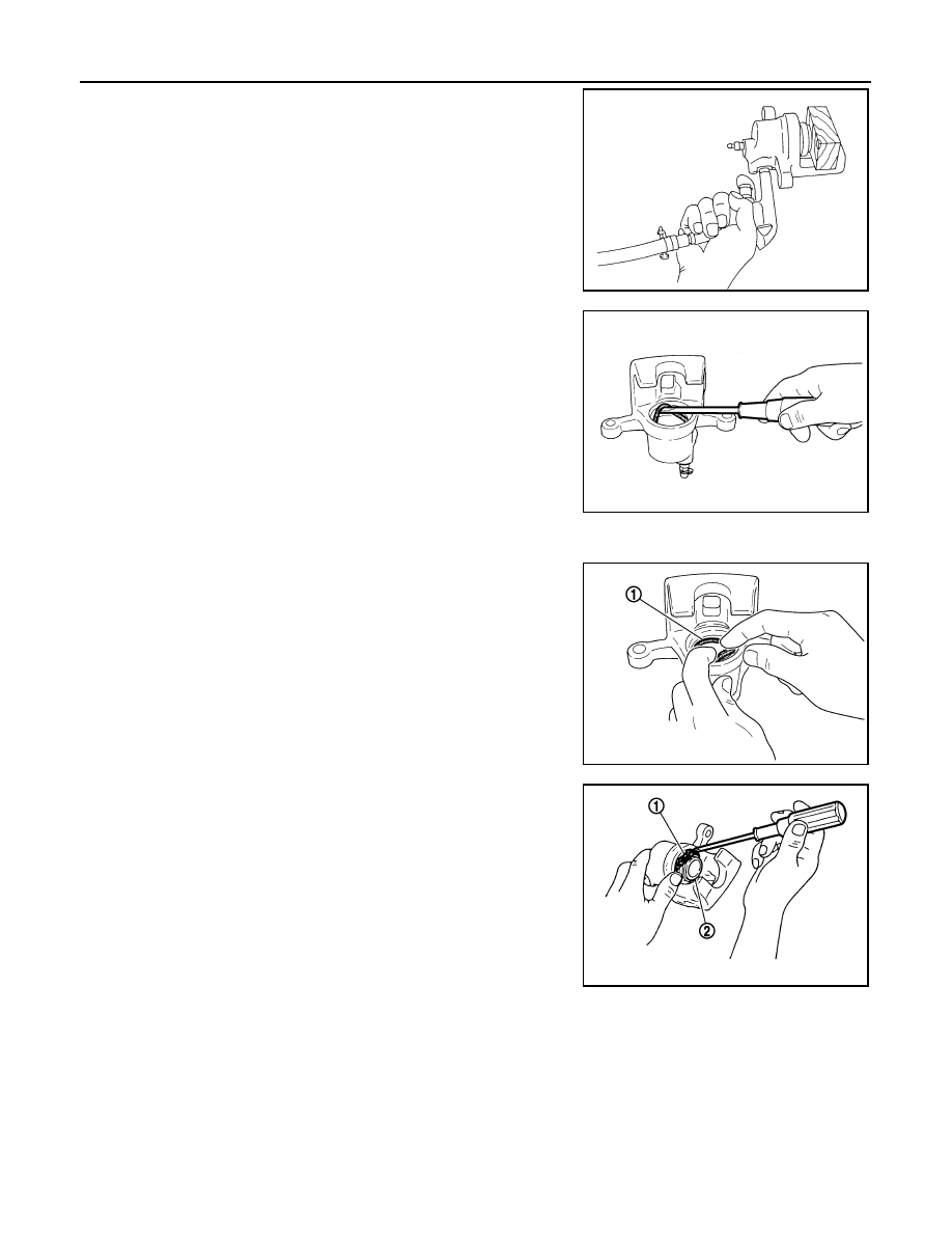
4.
Place a wooden block as shown in the figure, and blow air from
union bolt mounting hole to remove piston and piston boot.
CAUTION:
Never get fingers caught in the piston.
5.
Remove piston seal from cylinder body using suitable tool.
CAUTION:
Be careful not to damage a cylinder inner wall.
ASSEMBLY
1.
Apply polyglycol ether based lubricant to piston seal (1), and
install to cylinder body.
CAUTION:
Never reuse piston seal.
2.
Apply rubber grease to piston boot (1). Cover the piston (2) end
with the piston boot, and then install cylinder side lip on the pis-
ton boot securely into the groove on cylinder body.
CAUTION:
Never reuse piston boot.
BRD0041D
JPFIA0038ZZ
JPFIA0039ZZ
JPFIA0040ZZ