Nissan Qashqai J11. Manual - part 901
BR-76
< REMOVAL AND INSTALLATION >
[RHD]
VACUUM LINES
R9M
Removal and Installation
INFOID:0000000010450973
REMOVAL
1.
Remove the cowl top. Refer to
EXT-29, "Removal and Installation"
.
2.
Remove the air duct assembly to the electric throttle control actuator. Refer to
(K9K engine models),
(R9M engine models),
(MR20 engine models).
3.
Disconnect the vacuum hose from the engine intake manifold.
4.
Disconnect the vacuum hose from the brake booster.
5.
Disconnect the vacuum hose from the clip.
6.
Remove the vacuum hoses.
INSPECTION AFTER REMOVAL
Appearance
Check for correct assembly, damage and deterioration.
Check Valve Airtightness
• Use a handy vacuum pump (A) to check.
• Replace vacuum hose assembly if vacuum hose and check valve
are malfunctioning.
INSTALLATION
IInstall the vacuum hose and tube.
CAUTION:
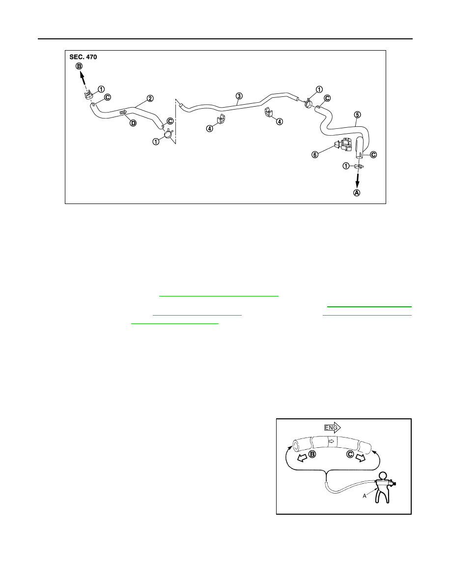
JPFIA0135ZZ
1.
Clamp
2.
Vacuum hose (built in check valve)
3.
Vacuum tube
4.
Clip
5.
Vacuum hose
6.
Grommet
A.
To vacuum pump
B.
To brake booster
C.
Paint mark
D.
Stamp indicating engine direction
When connected to the brake booster side (B) :
Vacuum should decrease within 1.3 kPa (10 mm-
Hg, 0.39 inHg, 0.013 bar) for 15 seconds under a
vacuum of -66.7 kPa (-500 mmHg, -19.70 inHg, -
0,667 bar).
When connected to the engine side (C) :
Vacuum should not exist.
JPFIA0024ZZ