Nissan Qashqai J11. Manual - part 897


  Index      Nissan     Nissan Qashqai J11 - Service and Repair Manual


Search            


Content   ..  895  896  897  898   ..


Nissan Qashqai J11. Manual - part 897


BR-60

< PERIODIC MAINTENANCE >

[RHD]

REAR DISC BRAKE

REAR DISC BRAKE

BRAKE PAD

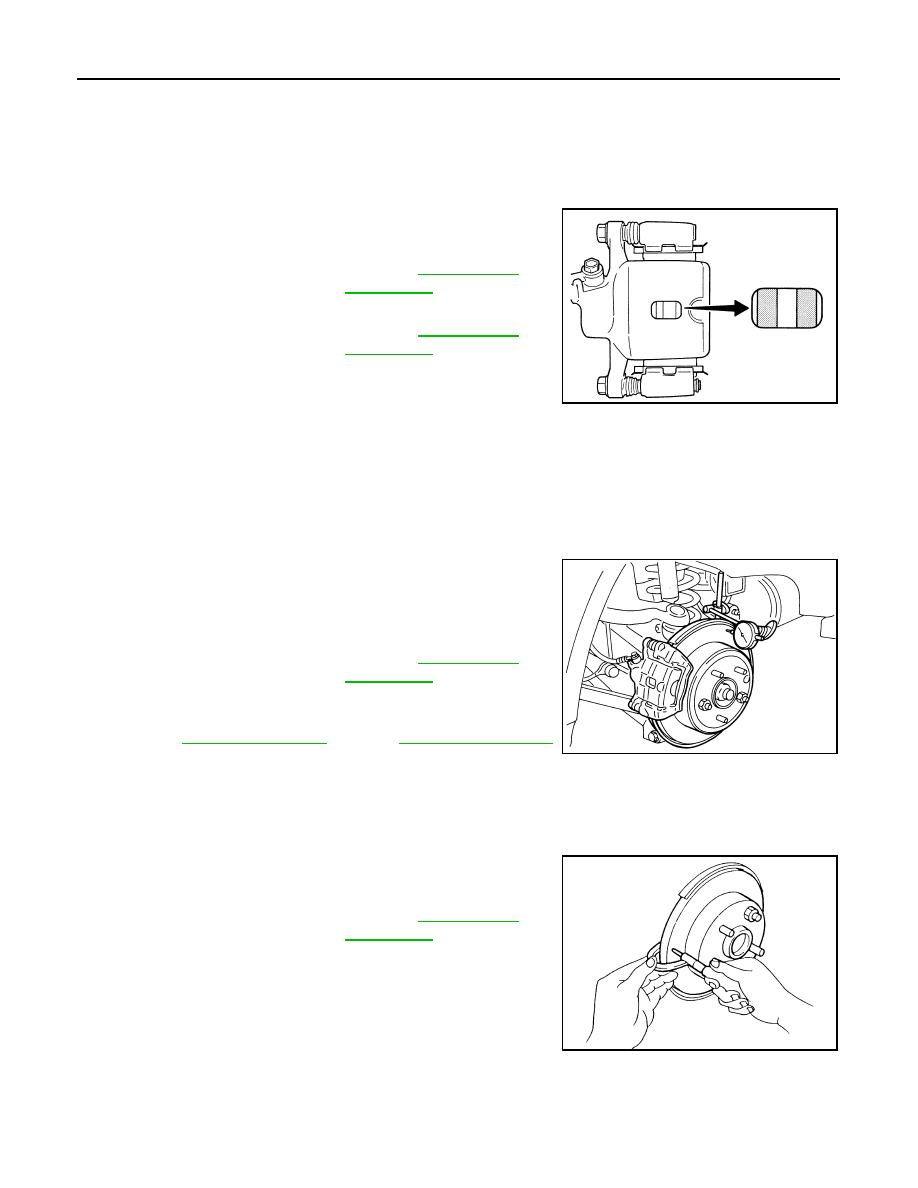
BRAKE PAD : Inspection

INFOID:0000000010305443

PAD WEAR

Check pad thickness from an inspection hole on cylinder body.
Check using a scale if necessary.

DISC ROTOR

DISC ROTOR : Inspection

INFOID:0000000010305444

APPEARANCE

Check surface of disc rotor for uneven wear, cracks, and serious damage. Replace if there are.

RUNOUT

1.

Fix the disc rotor to the wheel hub and bearing assembly with
wheel nuts (2 points at least).

2.

Inspect the runout with a dial gauge. [Measured at 10 mm (0.39
in) inside disc edge.]

NOTE:
Check the wheel bearing axial end play before the inspection.
Refer to 

RAX-3, "Inspection"

 (2WD), 

RAX-10, "Inspection"

(4WD).

3.

Find the installation position with a minimum runout by shifting the disc rotor-to-wheel hub and bearing
assembly installation position by one hole at a time if the runout exceeds the limit value.

4.

Replace or lathe the disc rotor if the runout exceeds the limit even after the above operation.

THICKNESS

Check the thickness of the disc rotor using a micrometer. Replace
the disc rotor if the thickness is below the wear limit.

Standard thickness

: Refer to 

BR-90, "Rear 

Disc Brake"

.

Wear limit thickness

: Refer to 

BR-90, "Rear 

Disc Brake"

.

BRA0010D

Runout limit

: Refer to 

BR-90, "Rear 

Disc Brake"

.

BRA0697D

Wear limit thickness

: Refer to 

BR-90, "Rear 

Disc Brake"

.

SFIA2284E

BRAKE PEDAL

BR-61

< REMOVAL AND INSTALLATION >

[RHD]

C

D

E

G

H

I

J

K

L

M

A

B

BR

N

O

P

REMOVAL AND INSTALLATION

BRAKE PEDAL

Exploded View

INFOID:0000000010305445

*

AT model

Removal and Installation

INFOID:0000000010471511

REMOVAL

1.

Remove instrument lower panel LH. Refer to 

IP-13, "Removal and Installation"

.

2.

Remove the knee protector. Refer to 

IP-12, "Exploded View"

.

3.

Remove snap pin and clevis pin from clevis of brake booster.

4.

Disconnect the harness connectors from the stop lamp switch and brake pedal position switch.

5.

Remove the accelerator pedal. Refer to 

ACC-3, "Removal and Installation"

.

6.

Remove the brake pedal

CAUTION:

Support the brake booster and master cylinder to prevent contact with other components.

INSTALLATION

Note the following, and installation is the reverse order of removal.
• Apply the multi-purpose grease to the clevis pin and the mating faces. (Not necessary if grease has been

already applied.)

NOTE:
The clevis pin may be inserted in either direction.

1.

Clevis pin

2.

Brake pedal assembly

3.

Stop lamp switch

4.

ASCD brake switch (shift lock brqke 
switch*)

5.

Clip

6.

Snap pin

: Apply multi-purpose grease.

Refer to 

GI-4, "Components"

 for symbols not described on the above.

E1FIA0147GB

BR-62

< REMOVAL AND INSTALLATION >

[RHD]

BRAKE PEDAL

Inspection and Adjustment

INFOID:0000000010305447

INSPECTION AFTER REMOVAL

• Check the following items and replace the brake pedal assembly if necessary.
- Check the brake pedal upper rivet for deformation.
- Check the brake pedal for bend, damage, and cracks on the welded parts.

• Check clevis pin and plastic stopper (A) for damage and deforma-

tion. If any is found, replace clevis pin.

ADJUSTMENT AFTER INSTALLATION

• Perform the brake pedal adjustment after installing the brake pedal assembly. Refer to 

BR-52, "Inspection

and Adjustment"

.

• Perform the accelerator pedal check after installing the accelerator pedal. Refer to 

ACC-3, "Inspection"

.

PFIA0756J

BRAKE PIPING

BR-63

< REMOVAL AND INSTALLATION >

[RHD]

C

D

E

G

H

I

J

K

L

M

A

B

BR

N

O

P

BRAKE PIPING

FRONT

FRONT : Exploded View

INFOID:0000000010305452

1.

Brake tube

2.

Brake booster

3.

Master cylinder assembly

4.

Connector

5.

ABS actuator and electric unit (con-
trol unit)

6.

Lock plate

7.

Brake hose

8.

Union bolt

A.

To front brake hose

B.

To rear brake tube

Refer to 

GI-4, "Components"

 for symbols in the figure.

E1FIA0149GB


Content   ..  895  896  897  898   ..