Nissan Qashqai J11. Manual - part 845
FRONT DRIVE SHAFT
FAX-67
< UNIT DISASSEMBLY AND ASSEMBLY >
[4WD]
C
E
F
G
H
I
J
K
L
M
A
B
FAX
N
O
P
UNIT DISASSEMBLY AND ASSEMBLY
FRONT DRIVE SHAFT
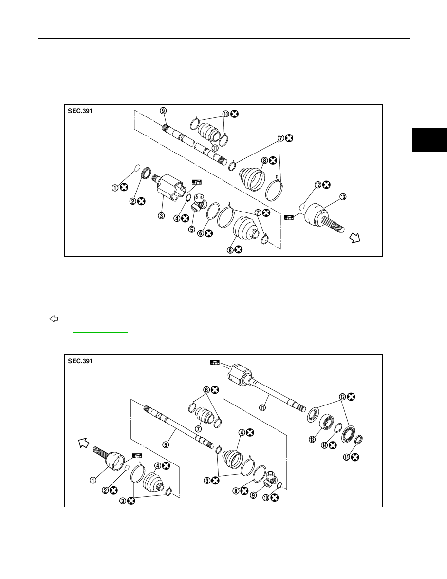
Exploded View
INFOID:0000000011722646
LHD models
RHD models - MR20DD
JPDIF0047ZZ
1.
Circular clip
2.
Dust shield
3.
Housing
4.
Snap ring
5.
Spider assembly
6.
Stopper ring
7.
Boot band
8.
Boot
9.
Shaft
10. Damper band
11.
Dynamic damper
12. Circular clip
13. Joint sub-assembly
Wheel side
Refer to
JPDIF0045ZZ
1.
Joint sub-assembly
2.
Circular clip
3.
Boot band
4.
Boot
5.
Shaft
6.
Damper band
7.
Dynamic damper
8.
Stopper ring
9.
Spider assembly
10. Snap ring
11.
Housing assembly
12. Dust shield