Nissan Qashqai J11. Manual - part 843


  Index      Nissan     Nissan Qashqai J11 - Service and Repair Manual


Search            


Content   ..  841  842  843  844   ..


Nissan Qashqai J11. Manual - part 843


FRONT DRIVE SHAFT BOOT

FAX-59

< REMOVAL AND INSTALLATION >

[4WD]

C

E

F

G

H

I

J

K

L

M

A

B

FAX

N

O

P

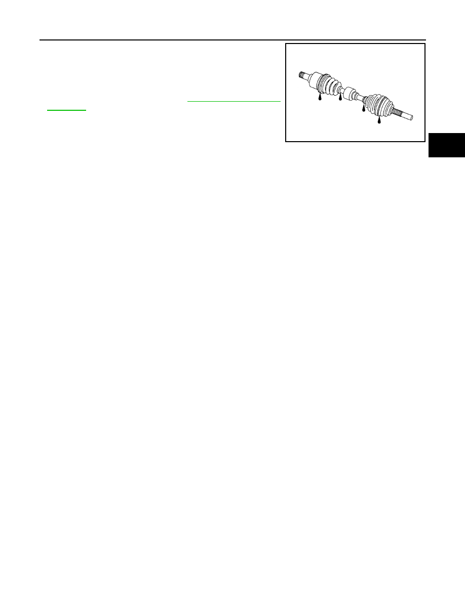
Check the following items, and replace the part if necessary.
• Move joint up/down, left/right, and in the axial directions. Check for

motion that is not smooth and for significant looseness.

• Check boot for cracks, damage, and leakage of grease.
• Check the wheel sensor harness to be sure the connectors are

fully seated. 

• Check the wheel alignment. Refer to 

FSU-7, "Wheel Alignment

Inspection"

.

SDIA1190J

FAX-60

< REMOVAL AND INSTALLATION >

[4WD]

FRONT DRIVE SHAFT

FRONT DRIVE SHAFT

Exploded View (LH)

INFOID:0000000010435950

Removal and Installation (LH)

INFOID:0000000010435951

REMOVAL

1.

Remove tires from vehicle.

2.

Remove the bolt (1) and separate the front wheel sensor from
the steering knuckle. Refer to 

BRC-138, "FRONT WHEEL SEN-

SOR : Removal and Installation"

.

CAUTION:

• Failure to separate the front wheel sensor from the steer-

ing knuckle may result in damage to the front wheel sen-
sor.

• Never pull on wheel sensor harness.

3.

Remove torque member mounting bolts. Hang torque member
not to interfere with work. Refer to 

BR-37, "BRAKE CALIPER

ASSEMBLY : Exploded View"

 (LHD), 

BR-80, "BRAKE CALIPER

ASSEMBLY : Exploded View"

 (RHD).

CAUTION:

Never depress brake pedal while brake caliper is removed.

4.

Put alignment marks (A) on disc brake rotor and wheel hub and
bearing. Remove disc brake rotor.

CAUTION:

Never drop the disc brake rotor.

5.

Remove cotter pin.

6.

Remove the nut retainer.

7.

Loosen the wheel hub lock nut from the drive shaft using power tool.

1.

Drive shaft

2.

Cotter pin

Refer to 

GI-4, "Components"

 for symbols in the figure.

E1DIA0230GB

ALDIA0526ZZ

JPDIG0066ZZ

FRONT DRIVE SHAFT

FAX-61

< REMOVAL AND INSTALLATION >

[4WD]

C

E

F

G

H

I

J

K

L

M

A

B

FAX

N

O

P

8.

Patch hub lock nut with a piece of wood. Hammer the wood to
disengage wheel hub and bearing assembly from drive shaft.
Remove the hub lock nut.

CAUTION:

• Never place the drive shaft joint at an extreme angle. Be

careful not to over extend the slide joint.

• Never allow drive shaft to hangdown  without support for

housing (or joint sub-assembly), shaft and the other parts.

NOTE:
Use a suitable puller iff drive shaft cannot be separated from the
wheel hub and bearing.

9.

Remove the lower nut and bolt from the steering knuckle (shown in explode). Separate the transverse link
from the steering knuckle. Refer to 

FSU-14, "Exploded View"

.

10. Separate drive shaft from wheel hub and bearing, Reposition the drive shaft aside with wire.

11. Remove drive shaft from transaxle assembly.

• Use the Tool (A) and a suitable tool (B) while inserting tip of

Tool (A) between housing and transaxle assembly.

CAUTION:

• Never place drive shaft joint at an extreme angle when

removing drive shaft. Also be careful not to overextend
slide joint.

• Confirm that the circular clip is attached to the drive

shaft.

INSTALLATION

Installation is in the reverse order of removal.
• Install a new differential side oil seal.

CAUTION:

Never reuse the differential side oil seal.

• Place Tool (A) onto transaxle assembly to prevent damage to the

differential side oil seal while inserting drive shaft. Slide drive shaft
sliding joint and tap with a suitable tool to install securely.

CAUTION:

Check that circular clip is completely engaged.

• Clean the matching surface of wheel hub lock nut and wheel hub and bearing.

CAUTION:

Never apply lubricating oil to these matching surface.

• Clean the mating surfaces of the joint sub-assembly and the wheel

hub and bearing. Apply Molykote M77 lubricant to the surface (A)
of the joint sub-assembly.

CAUTION:

Apply lubricant to cover the entire flat mating surface of the
joint sub-assembly.

NOTE:

JPDIG0070ZZ

Tool (A)

: KV40107500 ( –– )

JPDIF0004ZZ

Tool (A)

: KV38107900  ( –– )

JPDIF0023ZZ

Amount of lubricant

FAX-73, "Drive Shaft"

JPDIG0122ZZ

FAX-62

< REMOVAL AND INSTALLATION >

[4WD]

FRONT DRIVE SHAFT

Always check with the Parts Department for the latest parts information.

• Hold the wheel hub and bearing using a suitable tool. Tighten the wheel hub lock nut.

CAUTION:

• Since the drive shaft is assembled by press-fitting, use a torque wrench to tighten the wheel hub

lock nut. Do not use a power tool.

• Too much torque causes axle noise. Too little torque causes wheel bearing looseness. Tighten the

wheel hub lock nut to the specification.

• Align the matching marks that have been made during removal when reusing the disc brake rotor.
• When installing a cotter pin (1) and nut retainer (2), securely bend

the cotter pin to prevent rattles.

CAUTION:

Never reuse cotter pin.

• Perform the final tightening of each of parts under unladen condi-

tions, which were removed when removing wheel hub and bearing
and steering knuckle. 

Exploded View (RH)

INFOID:0000000010435952

MR20DD :

R9M :

JPDIF0295ZZ

1.

Cotter pin

2.

Drive shaft

3.

Plate

4.

Support bearing bracket

Refer to 

GI-4, "Components"

 for symbols in the figure

E1DIA0232GB


Content   ..  841  842  843  844   ..