Nissan Qashqai J11. Manual - part 832
FRONT DRIVE SHAFT BOOT
FAX-15
< REMOVAL AND INSTALLATION >
[2WD]
C
E
F
G
H
I
J
K
L
M
A
B
FAX
N
O
P
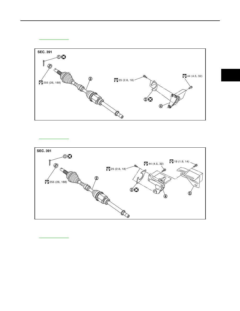
RIGHT SIDE (K9K)
RIGHT SIDE (MR16DDT)
1.
Cotter pin
2.
Drive shaft
3.
Plate
4.
Support bearing bracket
Refer to
E1DIA0233GB
1.
Cotter pin
2.
Drive shaft
3.
Plate
4.
Support bearing bracket
Refer to
E1DIA0513GB
1.
Cotter pin
2.
Drive shaft
3.
Plate
4.
Support bearing bracket
Refer to