Nissan Qashqai J11. Manual - part 830
PREPARATION
FAX-7
< PREPARATION >
[2WD]
C
E
F
G
H
I
J
K
L
M
A
B
FAX
N
O
P
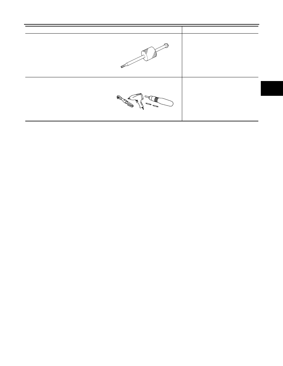
Sliding hammer
Removing drive shaft
Power tool
Loosening nuts, screws and bolts
Tool name
Description
ZZA0023D
PIIB1407E
|
|
|
PREPARATION FAX-7 < PREPARATION > [2WD] C E F G H I J K L M A B FAX N O P Sliding hammer Removing drive shaft Power tool Loosening nuts, screws and bolts Tool name Description ZZA0023D PIIB1407E |