Nissan Qashqai J11. Manual - part 794


  Index      Nissan     Nissan Qashqai J11 - Service and Repair Manual


Search            


Content   ..  792  793  794  795   ..


Nissan Qashqai J11. Manual - part 794


DLN-92

< UNIT DISASSEMBLY AND ASSEMBLY >

[TRANSFER: TY21C]

DRIVE PINION

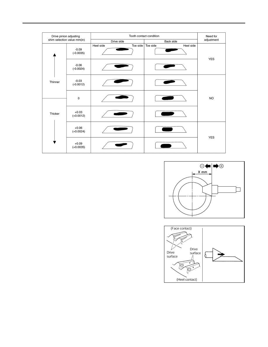
Tooth Contact Judgment Guide

8.

Follow the procedure below to adjust pinion height (dimension
X) if tooth contact is improper. For selecting adjusting shim, refer
to the latest parts information.

CAUTION:

If no adjusting shim with the calculated value is available,
select the thicker and closest one.

• Thicken the drive pinion adjusting shim to move the drive pin-

ion closer to the ring gear in case of face contact or heel con-
tact.

CAUTION:

Only one adjusting shim can be selected.

JSDIA4035GB

JSDIA1221ZZ

PDIA0440E

DRIVE PINION

DLN-93

< UNIT DISASSEMBLY AND ASSEMBLY >

[TRANSFER: TY21C]

C

E

F

G

H

I

J

K

L

M

A

B

DLN

N

O

P

• Thin the drive pinion adjusting shim to move the drive pinion

farther from the ring gear in case of flank contact or toe con-
tact.

CAUTION:

Only one adjusting shim can be selected.

COMPANION FLANGE RUNOUT

1.

Fit a dial indicator onto the companion flange face (inner side of
the propeller shaft mounting bolt holes).

2.

Rotate the companion flange to check for runout.

3.

Fit suitable tool to the inner side of the companion flange (socket
diameter).

4.

Rotate the companion flange to check for runout.

5.

Follow the procedure below to adjust if runout value is outside
the repair limit.

a.

Check for runout while changing the phase between companion
flange and drive pinion in 90

°

 steps. Then search for the mini-

mum point.

b.

Replace companion flange if runout value is still outside the limit
after the phase has been changed.

c.

Adjust assembly status of the pinion bearing and drive pinion, or
replace pinion bearing assembly if runout is outside the standard
after the companion flange is replaced.

Inspection

INFOID:0000000010755206

INSPECTION AFTER DISASSEMBLY

Check items below. If necessary, replace them with new ones.

Gear and Shaft 

Check gear face and shaft for wear, cracks, damage, and seizure.

CAUTION:

Replace ring gear and drive pinion as a set (hypoid gear set) if any malfunction is detected on the ring
gear or drive pinion.

Bearing

Check for seizure, peeling, wear, corrosion, sticking, unusual noise, roughness in hand turning, and other
damage.

Shim

Check for seizure, damage, and unusual wear.

PDIA0441E

Companion flange runout

: Refer to 

DLN-97, "Com-

panion Flange Runout"

.

Companion flange runout

: Refer to 

DLN-97, "Com-

panion Flange Runout"

.

JSDIA3981ZZ

DLN-94

< UNIT DISASSEMBLY AND ASSEMBLY >

[TRANSFER: TY21C]

TRANSFER CASE

TRANSFER CASE

Exploded View

INFOID:0000000010755207

MR20DD models

JSDIA5341GB

Pinion lock nut

Companion flange

Dust cover

Oil seal

Pinion bearing assembly

O-ring

Drive pinion adjusting shim

Drive pinion

O-ring

Oil seal

Dowel pin

Plug

Gasket

Transfer case

Baffle plate

Ring gear bearing adjusting shim 
(transfer case side)

Ring gear bearing (transfer case 
side)

Ring gear

Ring gear shaft

Ring gear shaft oil seal

Ring gear bearing (transfer cover 
side)

Ring gear bearing adjusting shim 
(transfer cover side)

Oil seal

O-ring

Transfer cover

Oil seal

Filler plug

Drain plug

Oil seal lip

Comply with the assembly procedure 
when tightening. Refer to 

DLN-87, 

"Assembly"

.

: N·m (kg-m, in-lb)

: N·m (kg-m, ft-lb)

: Always replace after every disassembly.

: Select with proper thickness.

TRANSFER CASE

DLN-95

< UNIT DISASSEMBLY AND ASSEMBLY >

[TRANSFER: TY21C]

C

E

F

G

H

I

J

K

L

M

A

B

DLN

N

O

P

Disassembly

INFOID:0000000010755208

1.

Remove transfer cover. Refer to 

DLN-79, "Disassembly"

.

2.

Remove ring gear shaft assembly. Refer to 

DLN-83, "Disassembly"

.

3.

Remove drive pinion assembly. Refer to 

DLN-87, "Disassembly"

.

4.

Remove O-ring from transfer case.

CAUTION:

• Never use a suitable tool.
• Never damage transfer case.

5.

Remove oil seals 

.

CAUTION:

Never damage transfer case.

6.

Remove baffle plate 

.

7.

Remove the ring gear bearing adjusting shim (transfer case
side) 

 and ring gear bearing outer race (transfer case side) 

by tapping from the 2 cutouts (

) on the transfer case.

CAUTION:

Never damage transfer case.

8.

Remove plug and gasket.

9.

Perform inspection after disassembly. Refer to 

DLN-96, "Inspec-

tion"

.

Assembly

INFOID:0000000010755209

1.

Select the ring gear bearing adjusting shim (transfer case side). Refer to 

DLN-88, "Adjustment"

.

: Apply transfer oil.

*

: Apply anti-corrosive oil.

: Apply multi-purpose grease.

JSDIA3983ZZ

JSDIA3982ZZ

JSDIA3984ZZ


Content   ..  792  793  794  795   ..