Nissan Qashqai J11. Manual - part 715


  Index      Nissan     Nissan Qashqai J11 - Service and Repair Manual


Search            


Content   ..  713  714  715  716   ..


Nissan Qashqai J11. Manual - part 715


COMPONENT PARTS

TM-435

< SYSTEM DESCRIPTION >

[CVT: RE0F10G]

C

E

F

G

H

I

J

K

L

M

A

B

TM

N

O

P

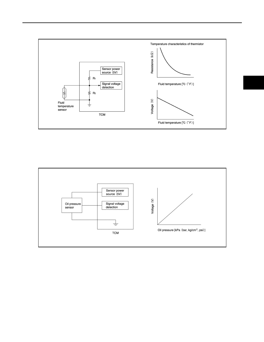
• The fluid temperature sensor uses a thermistor, and changes the signal voltage by converting changes in the

CVT fluid temperature to a resistance value. TCM evaluates the CVT fluid temperature from the signal volt-
age value. 

CVT CONTROL SYSTEM : Primary Pressure Sensor

INFOID:0000000010245525

• The primary pressure sensor is installed to control valve.
• The primary pressure sensor detects the pressure applied to the primary pulley. 
• When pressure is applied to the ceramic device in the primary pressure sensor, the ceramic device is

deformed, resulting in voltage change. TCM evaluates the primary pressure from its voltage change. Voltage
is increased along with pressure increase. 

CVT CONTROL SYSTEM : Secondary Pressure Sensor

INFOID:0000000010245526

• The secondary pressure sensor is installed to control valve.
• The secondary pressure sensor detects the pressure applied to the secondary pulley. 

JSDIA1825GB

JSDIA1831GB

TM-436

< SYSTEM DESCRIPTION >

[CVT: RE0F10G]

COMPONENT PARTS

• When pressure is applied to the metal diaphragm in the secondary pressure sensor, the metal diaphragm is

deformed, resulting in voltage change. TCM evaluates the secondary pressure from its voltage change. Volt-
age is increased along with pressure increase. 

CVT CONTROL SYSTEM : Primary Pressure Solenoid Valve

INFOID:0000000010245527

• The primary pressure solenoid valve is installed to control valve.
• The primary pressure solenoid valve controls the primary reducing valve. For information about the primary

reducing valve, refer to 

TM-444, "TRANSAXLE : Component Description"

.

• The primary pressure solenoid valve uses the linear solenoid valve

[N/H (normal high) type].
NOTE:
• The principle of the linear solenoid valve utilizes the fact that the

force pressing on the valve spool installed inside the coil
increases nearly in proportion to the current. This allows it to pro-
duce a fluid pressure that is proportional to this pressing force.

• The N/H (normal high) produces hydraulic control when the coil

is not energized.

CVT CONTROL SYSTEM : Secondary Pressure Solenoid Valve

INFOID:0000000010245528

• The secondary pressure solenoid valve is installed to control valve.
• The secondary pressure solenoid valve controls the secondary reducing valve. For information about the

secondary reducing valve, refer to 

TM-444, "TRANSAXLE : Component Description"

.

• The secondary pressure solenoid valve uses the linear solenoid

valve [N/H (normal high) type].
NOTE:
• The principle of the linear solenoid valve utilizes the fact that the

force pressing on the valve spool installed inside the coil
increases nearly in proportion to the current. This allows it to pro-
duce a fluid pressure that is proportional to this pressing force.

• The N/H (normal high) produces hydraulic control when the coil

is not energized.

CVT CONTROL SYSTEM : Select Solenoid Valve

INFOID:0000000010245529

• The select solenoid valve is installed to control valve.
• The select solenoid valve adjusts the forward clutch engaging pressure and the reverse brake engaging

pressure. For information about the forward clutch and reverse brake, refer to 

TM-444, "TRANSAXLE :

Component Description"

.

JSDIA1831GB

JSDIA3647GB

JSDIA3647GB

COMPONENT PARTS

TM-437

< SYSTEM DESCRIPTION >

[CVT: RE0F10G]

C

E

F

G

H

I

J

K

L

M

A

B

TM

N

O

P

• The select solenoid valve uses the linear solenoid valve [N/H (nor-

mal high) type].
NOTE:
• The principle of the linear solenoid valve utilizes the fact that the

force pressing on the valve spool installed inside the coil
increases nearly in proportion to the current. This allows it to pro-
duce a fluid pressure that is proportional to this pressing force.

• The N/H (normal high) type produces hydraulic control when the

coil is not energized.

CVT CONTROL SYSTEM : Torque Converter Clutch Solenoid Valve

INFOID:0000000010245530

• The torque converter clutch solenoid valve is installed to control valve.
• The torque converter clutch solenoid valve controls the torque converter clutch control valve. For information

about the torque converter clutch control valve, refer to 

TM-444, "TRANSAXLE : Component Description"

.

• The torque converter clutch solenoid valve utilizes a linear sole-

noid valve [N/L (normal low) type].
NOTE:
• The principle of the linear solenoid valve utilizes the fact that the

force pressing on the valve spool installed inside the coil
increases nearly in proportion to the current. This allows it to pro-
duce a fluid pressure that is proportional to this pressing force.

• The N/L (normal low) type does not produce hydraulic control

when the coil is not energized.

CVT CONTROL SYSTEM : Line Pressure Solenoid Valve

INFOID:0000000010245531

• The line pressure solenoid valve is installed to control valve.
• The line pressure solenoid valve controls the pressure regulator valve. For information about the pressure

regulator valve, refer to 

TM-444, "TRANSAXLE : Component Description"

.

• The line pressure solenoid valve uses the linear solenoid valve [N/

H (normal high) type].
NOTE:
• The principle of the linear solenoid valve utilizes the fact that the

force pressing on the valve spool installed inside the coil
increases nearly in proportion to the current. This allows it to pro-
duce a fluid pressure that is proportional to this pressing force.

• The N/H (normal high) produces hydraulic control when the coil

is not energized.

CVT CONTROL SYSTEM : G SENSOR

INFOID:0000000010304575

• G sensor detects front/rear G and inclination applied to the vehicle.
• G sensor converts front/rear G and inclination applied to the vehi-

cle to voltage signal. TCM evaluates front/rear G and inclination
angle of the vehicle from the voltage signal.

JSDIA3647GB

JSDIA3648GB

JSDIA3647GB

JSDIA3076ZZ

TM-438

< SYSTEM DESCRIPTION >

[CVT: RE0F10G]

COMPONENT PARTS

CVT CONTROL SYSTEM : Electric Oil Pump

INFOID:0000000010304576

• It is operated with the signal from TCM during stop/start operation.

Oil pressure required for restart of the engine is obtained instead of
the mechanical oil pump.

• During operation, the status signal (Duty) is sent to TCM.

Electric oil pump status signal characteristics

CVT CONTROL SYSTEM : Electric Oil Pump Relay

INFOID:0000000010304577

• The electric oil pump relay is deactivated when the vehicle speed reaches 11 km/h (7 MPH) or more and

becomes activated when it reaches 6 km/h (4 MPH) or less.

• It is ON with the signal from TCM. It is ready for operation of the electric oil pump by TCM.

CVT CONTROL SYSTEM : Manual Mode Switch

INFOID:0000000010497871

• The manual mode switch 

 [mode select switch and position

select switch (upshift/downshift)] is installed in the CVT shift selec-
tor assembly.

• The mode select switch detects the position (the main shift gate

side or manual shift gate side) of the selector lever and transmits a
manual mode signal or a not manual mode signal to the combina-
tion meter. Then, the TCM receives a manual mode signal or non-
manual mode signal from the combination meter.

• The position select switch (upshift) detects that the selector lever is

shifted to the upshift side of the manual shift gate and transmits a
manual mode upshift signal to the combination meter. Then, the
TCM receives a manual mode upshift signal from the combination
meter.

• The position select switch (downshift) detects that the selector lever is shifted to the downshift side of the

manual shift gate and transmits a manual mode downshift signal to the combination meter. Then, the TCM
receives a manual mode downshift signal from the combination meter.

CVT CONTROL SYSTEM : Shift Position Indicator

INFOID:0000000010245533

TCM transmits shift position signal to combination meter via CAN communication. The actual shift position is
displayed on combination meter according to the signal.

SHIFT LOCK SYSTEM

: Electric oil pump

JSDIA5233ZZ

Status signal (Duty)

Condition

0 %

Electric oil pump power OFF

10 %

20 %

Overheat protection

30 %

In normal stop

40 %

In activation

50 %

In normal operation

60 – 100 %

Possible malfunction

JSDIA5308ZZ


Content   ..  713  714  715  716   ..