Nissan Qashqai J11. Manual - part 714
COMPONENT PARTS
TM-431
< SYSTEM DESCRIPTION >
[CVT: RE0F10G]
C
E
F
G
H
I
J
K
L
M
A
B
TM
N
O
P
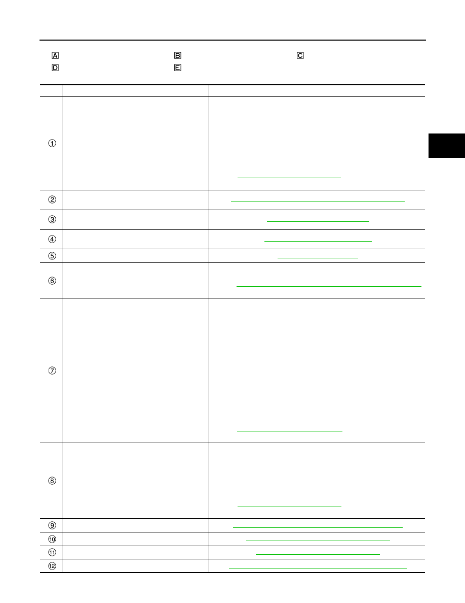
CVT shift selector assembly
Center console, under
Engine room
Engine room, LH
Transaxle assembly
No.
Component
Function
Combination meter
Mainly transmits the following signal to TCM via CAN communication.
• Manual mode downshift signal
• Manual mode upshift signal
• Manual mode signal
• Non-manual mode signal
• ECO mode switch signal
*3
Mainly receives the following signals from TCM via CAN communication.
• Shift position signal
• Manual mode shift refusal signal
Refer to
MWI-6, "Component Parts Location"
for detailed installation loca-
tion.
Shift position indicator
(On the combination meter)
TM-438, "CVT CONTROL SYSTEM : Shift Position Indicator"
Stop/start indicator lamp
(On the combination meter)
EC9-24, "Stop/Start Indicator Lamp"
Malfunction indicator lamp (MIL)
(On the combination meter)
EC9-23, "Malfunction Indicator Lamp"
ECO mode switch
*3
BCM
Mainly transmits the following signal to TCM via CAN communication.
• Stop lamp switch signal
Refer to
BCS-7, "BODY CONTROL SYSTEM : Component Parts Location"
for detailed installation location.
ECM
Mainly transmits the following signal to TCM via CAN communication.
• Engine and CVT integrated control signal
NOTE:
General term for the communication (torque-down permission, torque-
down request, etc.) exchanged between the ECM and TCM.
• Engine speed signal
• Engine coolant temperature signal
• Accelerator pedal position signal
• Closed throttle position signal
• Idle signal
• Stop/start readiness signal
*1
Mainly receives the following signals from TCM via CAN communication.
• Malfunctioning indicator lamp signal
• Stop/start enable OK signal
*1
• ECO mode signal
*3
EC9-12, "Component Parts Location"
for detailed installation loca-
tion.
ABS actuator and electric unit (control unit)
Mainly transmits the following signal to TCM via CAN communication.
• ABS operation signal
• TCS operation signal
• VDC operation signal
• ABS malfunction signal
• Vehicle speed signal
• Decel G signal
Refer to
BRC-8, "Component Parts Location"
for detailed installation loca-
tion.
Manual mode switch
TM-438, "CVT CONTROL SYSTEM : Manual Mode Switch"
G sensor
TM-437, "CVT CONTROL SYSTEM : G SENSOR"
TCM
TM-432, "CVT CONTROL SYSTEM : TCM"
Electric oil pump relay