Nissan Qashqai J11. Manual - part 709


  Index      Nissan     Nissan Qashqai J11 - Service and Repair Manual


Search            


Content   ..  707  708  709  710   ..


Nissan Qashqai J11. Manual - part 709


FLUID COOLER SYSTEM

TM-411

< REMOVAL AND INSTALLATION >

[CVT: RE0F10D]

C

E

F

G

H

I

J

K

L

M

A

B

TM

N

O

P

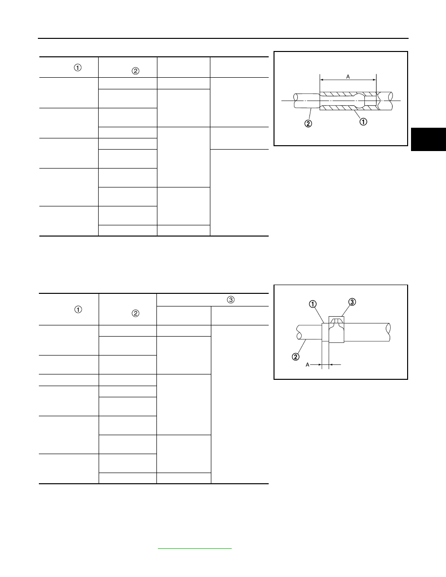
• Refer to the followings when installing fluid cooler hose.

• Refer to the followings when installing hose clamp.

CAUTION:

Hose clamp should not interfere with the bulge of fluid cooler tube.

Inspection

INFOID:0000000010589399

INSPECTION AFTER INSTALLATION

Start the engine and check visually that there is no leakage of CVT fluid.

ADJUSTMENT AFTER INSTALLATION

Adjust the CVT fluid level. Refer to 

TM-380, "Adjustment"

.

Hose 

Installation side 

tube 

Direction of paint 

mark

Hose insertion 

depth (A)

Fluid cooler hose B

Fluid cooler tube A

Frontward 

Hose end reaches 
the 2-stage bulge.

Fluid cooler tube 
assembly A

Leftward

Fluid cooler hose C

Fluid cooler tube 
assembly A

CVT fluid cooler

Frontward 

Hose end reaches 
the end of tube

Fluid cooler hose D

CVT fluid cooler

Fluid cooler tube 
assembly B

Hose end reaches 
the 2-stage bulge. 

Fluid cooler hose E

Fluid cooler tube 
assembly B

Fluid cooler tube 
assembly A

Leftward 

Fluid cooler hose F

Fluid cooler tube 
assembly A

CVT oil warmer

Upward

SCIA7203E

Hose 

Installation side 

tube 

Hose clamp 

Direction of tab

Clamping position 

(A)

Fluid cooler hose B

Fluid cooler tube A

Upward

5 – 9 mm (0.20 – 
0.35 in) from hose 
end

Fluid cooler tube 
assembly A

Leftward

Fluid cooler hose C

Fluid cooler tube 
assembly A

CVT fluid cooler

Upward

Fluid cooler hose D

CVT fluid cooler

Fluid cooler tube 
assembly B

Fluid cooler hose E

Fluid cooler tube 
assembly B

Fluid cooler tube 
assembly A

Leftward

Fluid cooler hose F

Fluid cooler tube 
assembly A

CVT oil warmer

Upward

JSDIA2424ZZ

TM-412

< REMOVAL AND INSTALLATION >

[CVT: RE0F10D]

CVT OIL WARMER

CVT OIL WARMER

Exploded View

INFOID:0000000010589400

Removal and Installation

INFOID:0000000010589401

REMOVAL

WARNING:

Never remove the radiator cap when the engine is hot. Serious burns could occur from high pressure
coolant escaping from the radiator. Wrap a thick cloth around the cap. Slowly turn it a quarter turn to
allow built-up pressure to escape. Carefully remove the cap by turning it all the way.

CAUTION:

Perform when the engine is cold.
NOTE:
When removing components such as hoses, tubes/lines, etc., cap or plug openings to prevent fluid/coolant
from spilling.

1.

Remove the battery mounting bracket assembly and battery mounting bracket. Refer to 

PG-154,

"Exploded View"

.

2.

Remove the harness bracket mounting nuts (

) and remove

the harness bracket 

 from the vehicle.

3.

Pull out water hoses from CVT oil warmer. Refer to 

TM-405,

"Removal and Installation"

.

4.

Pull out fluid cooler hoses from CVT oil warmer. Refer to 

TM-

409, "Removal and Installation"

.

Transaxle assembly

CVT oil warmer

: N·m (kg-m, in-lb)

JSDIA4994GB

: Vehicle front

JSDIA6041ZZ

CVT OIL WARMER

TM-413

< REMOVAL AND INSTALLATION >

[CVT: RE0F10D]

C

E

F

G

H

I

J

K

L

M

A

B

TM

N

O

P

5.

Remove mounting bolt (

) and remove CVT oil warmer from

transaxle assembly.

INSTALLATION

Installation is in the reverse order of removal.

Inspection

INFOID:0000000010589402

INSPECTION AFTER INSTALLATION

Start the engine and check visually that there is no leakage of CVT fluid and engine coolant.

ADJUSTMENT AFTER INSTALLATION

Adjust the CVT fluid level. Refer to 

TM-380, "Adjustment"

.

JSDIA6042ZZ

TM-414

< REMOVAL AND INSTALLATION >

[CVT: RE0F10D]

PLUG

PLUG

Description

INFOID:0000000010589403

Replace the O-ring if oil leakage or exudes from the plug.

Exploded View

INFOID:0000000010589404

Removal and Installation

INFOID:0000000010589405

REMOVAL

1.

Remove front fender protector (LH). Refer to 

EXT-32, "Removal and Installation"

.

2.

Remove the plug and O-ring.

INSTALLATION

Installation is in the reverse order of removal.

CAUTION:

• Never reuse O-ring.
• Apply CVT fluid to O-ring.

Inspection and Adjustment

INFOID:0000000010589406

INSPECTION AFTER INSTALLATION

Start the engine and check visually that there is no leakage of CVT fluid.

ADJUSTMENT AFTER INSTALLATION

Adjust the CVT fluid level. Refer to 

TM-380, "Adjustment"

.

Transaxle assembly

O-ring

Plug

: Always replace after every disassembly.

: N·m (kg-m, ft-lb)

: Apply CVT fluid

JSDIA3622GB


Content   ..  707  708  709  710   ..