Nissan Qashqai J11. Manual - part 683


  Index      Nissan     Nissan Qashqai J11 - Service and Repair Manual


Search            


Content   ..  681  682  683  684   ..


Nissan Qashqai J11. Manual - part 683


P0706 TRANSMISSION RANGE SENSOR A

TM-307

< DTC/CIRCUIT DIAGNOSIS >

[CVT: RE0F10D]

C

E

F

G

H

I

J

K

L

M

A

B

TM

N

O

P

Is the check result normal?

YES

>> GO TO 8.

NO

>> Repair or replace malfunctioning parts.

8.

DETECT MALFUNCTIONING ITEMS

Check the following items:
• Open circuit or short circuit in harness between ignition switch and IPDM E/R. Refer to 

PG-56, "Wiring Dia-

gram - IGNITION POWER SUPPLY -"

.

• Short circuit in harness between IPDM E/R harness connector terminal 101 and transmission range switch

harness connector terminal 3.

• 10A fuse (No. 67, located in the IPDM E/R). Refer to 

PG-101, "Fuse, Connector and Terminal Arrangement"

.

• IPDM E/R

Is the check result normal?

YES

>> Check intermittent incident. Refer to 

GI-41, "Intermittent Incident"

.

NO

>> Repair or replace malfunctioning parts.

Component Inspection

INFOID:0000000010589299

1.

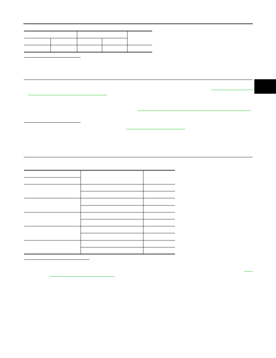
CHECK TRANSMISSION RANGE SWITCH

Check continuity between transmission range switch connector terminals.

Is the inspection result normal?

YES

>> INSPECTION END

NO

>> There is a malfunction of transmission range switch. Replace transaxle assembly. Refer to 

TM-

415, "Removal and Installation"

.

IPDM E/R

Transmission range switch

Continuity

Connector

Terminal

Connector

Terminal

F90

101

F61

3

Existed

Transmission range switch

Condition

Continuity

Terminal

1 – 2

Manual lever: “P” and “N” positions

Existed

Other than the above

Not existed

3 – 4

Manual lever: “P” position

Existed

Other than the above

Not existed

3 – 5

Manual lever: “R” position

Existed

Other than the above

Not existed

3 – 6

Manual lever: “N position

Existed

Other than the above

Not existed

3 – 7

Manual lever: “D” position

Existed

Other than the above

Not existed

TM-308

< DTC/CIRCUIT DIAGNOSIS >

[CVT: RE0F10D]

P0712 TRANSMISSION FLUID TEMPERATURE SENSOR A

P0712 TRANSMISSION FLUID TEMPERATURE SENSOR A

DTC Logic

INFOID:0000000010589300

DTC DETECTION LOGIC

DTC CONFIRMATION PROCEDURE

1.

PREPARATION BEFORE WORK

If another "DTC CONFIRMATION PROCEDURE" occurs just before, turn ignition switch OFF and wait for at
least 10 seconds, then perform the next test.

>> GO TO 2.

2.

PERFORM DTC CONFIRMATION PROCEDURE

1.

Start the engine and wait for 10 seconds or more.

2.

Check the first trip DTC.

Is “P0712” detected?

YES

>> Go to 

TM-308, "Diagnosis Procedure"

.

NO

>> INSPECTION END

Diagnosis Procedure

INFOID:0000000010589301

1.

CHECK CIRCUIT BETWEEN TCM AND CVT UNIT

1.

Turn ignition switch OFF.

2.

Disconnect TCM connector and CVT unit connector. 

3.

Check continuity between TCM harness connector terminal and ground.

Is the inspection result normal?

YES

>> GO TO 2.

NO

>> Repair or replace malfunctioning part.

2.

CHECK CVT UNIT TERMINAL CODE ASSEMBLY

Check continuity between CVT unit connector terminal and ground.

Is the inspection result normal?

YES

>> GO TO 3.

NO

>> There is a malfunction of the CVT unit terminal code assembly. Replace the transaxle assembly.

Refer to 

TM-415, "Removal and Installation"

.

3.

CHECK CVT FLUID TEMPERATURE SENSOR

DTC

CONSULT screen terms

(Trouble diagnosis content)

DTC detection condition

Possible causes

P0712

FLUID TEMP SENSOR A
(Transmission Fluid Tempera-
ture Sensor A Circuit Low)

When all of the following conditions are satis-
fied and this state is maintained for 5 seconds:
• TCM power supply voltage: More than 11 V
• Fluid temperature sensor detection voltage: 

0.15 V or less

• Harness or connector

(CVT fluid temperature sensor circuit is 
shorted to ground)

• CVT fluid temperature sensor

TCM

Continuity

Connector

Terminal

F2

12

Ground

Not existed

CVT unit

Continuity

Connector

Terminal

F58

12

Ground

Not existed

P0712 TRANSMISSION FLUID TEMPERATURE SENSOR A

TM-309

< DTC/CIRCUIT DIAGNOSIS >

[CVT: RE0F10D]

C

E

F

G

H

I

J

K

L

M

A

B

TM

N

O

P

Check resistance between CVT unit connector terminals.

Is the inspection result normal?

YES

>> Check intermittent incident. Refer to 

GI-41, "Intermittent Incident"

.

NO

>> There is a malfunction of the CVT fluid temperature sensor. Replace the transaxle assembly.

Refer to 

TM-415, "Removal and Installation"

.

CVT unit

Condition

Resistance

(Approx.)

Connector

Terminal

F207

12 – 18

CVT fluid temperature: 20

°

C (68

°

F)

6.5 k

CVT fluid temperature: 50

°

C (122

°

F)

2.2 k

CVT fluid temperature: 80

°

C (176

°

F)

0.87 k

TM-310

< DTC/CIRCUIT DIAGNOSIS >

[CVT: RE0F10D]

P0713 TRANSMISSION FLUID TEMPERATURE SENSOR A

P0713 TRANSMISSION FLUID TEMPERATURE SENSOR A

DTC Logic

INFOID:0000000010589302

DTC DETECTION LOGIC

DTC CONFIRMATION PROCEDURE

CAUTION:

Be careful of the driving speed.

1.

PREPARATION BEFORE WORK

If another "DTC CONFIRMATION PROCEDURE" occurs just before, turn ignition switch OFF and wait for at
least 10 seconds, then perform the next test.

>> GO TO 2.

2.

PERFORM DTC CONFIRMATION PROCEDURE

1.

Start the engine.

2.

Maintain the following condition for 10 seconds or more.

3.

Stop the vehicle.

4.

Check the first trip DTC.

Is “P0713” detected?

YES

>> Go to 

TM-310, "Diagnosis Procedure"

.

NO

>> INSPECTION END

Diagnosis Procedure

INFOID:0000000010589303

1.

CHECK CIRCUIT BETWEEN TCM AND CVT UNIT (PART 1)

1.

Turn ignition switch OFF.

2.

Disconnect TCM connector and CVT unit connector. 

3.

Check continuity between TCM harness connector terminals and CVT unit harness connector terminals.

Is the inspection result normal?

YES

>> GO TO 2.

NO

>> Repair or replace malfunctioning parts.

2.

CHECK CIRCUIT BETWEEN TCM AND CVT UNIT (PART 2)

1.

Turn ignition switch ON.

2.

Check voltage between TCM harness connector terminal and ground.

DTC

CONSULT screen terms

(Trouble diagnosis content)

DTC detection condition

Possible causes

P0713

FLUID TEMP SENSOR A
(Transmission Fluid Tempera-
ture Sensor A Circuit High)

When all of the following conditions are satis-
fied and this state is maintained for 5 seconds:
• TCM power supply voltage: More than 11 V
• Vehicle speed: More than 10 km/h (7 MPH)
• Fluid temperature sensor detection voltage: 

2.48 V or more

• Harness or connector

(CVT fluid temperature sensor circuit is 
open or shorted to power supply)

• CVT fluid temperature sensor

Vehicle speed

: 20 km/h (12 MPH) or more

TCM

CVT unit

Continuity

Connector

Terminal

Connector

Terminal

F2

11

F58

18

Existed

12

12


Content   ..  681  682  683  684   ..