Nissan Qashqai J11. Manual - part 667


  Index      Nissan     Nissan Qashqai J11 - Service and Repair Manual


Search            


Content   ..  665  666  667  668   ..


Nissan Qashqai J11. Manual - part 667


SYSTEM

TM-243

< SYSTEM DESCRIPTION >

[CVT: RE0F10D]

C

E

F

G

H

I

J

K

L

M

A

B

TM

N

O

P

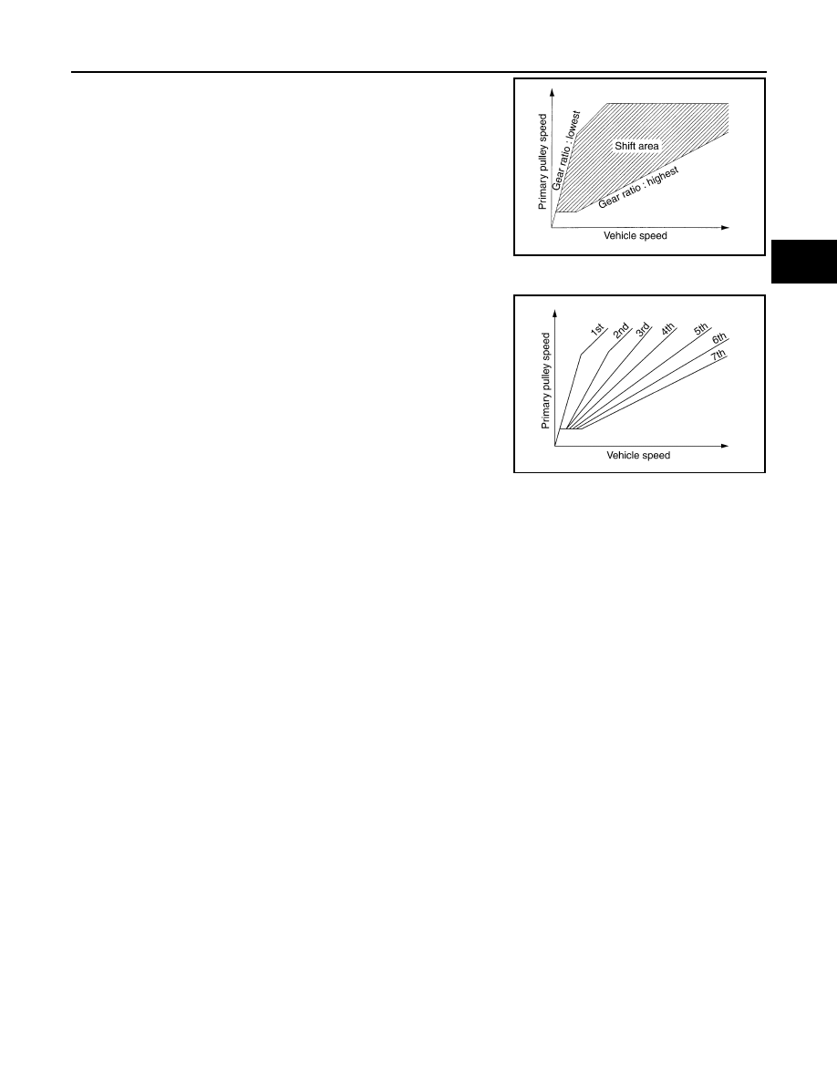
Gear shifting is performed in all shifting ranges from the lowest to
the highest gear ratio. 

• M Position (Manual Mode)

When the selector lever is put in the manual shift gate side, the
fixed changing gear line is set. By moving the selector lever to +
side or - side, the manual mode switch is changed over, and shift
change like M/T becomes possible following the changing gear set
line step by step.

- Manual Mode Information

The TCM transmits the manual mode shift refusal signal to the combination meter if the TCM refuses the
transmission from the driving status of vehicle when the selector lever shifts to UP side (+ side) or DOWN
side (

side). The combination meter blinks shift indicator on the combination meter and sounds the buzzer to

indicate the driver that the shifting is not performed when receiving this signal. However, the TCM does not
transmit the manual mode shift refusal signal in the conditions as per the following.

• When the selector lever shifts to DOWN side (

 side) while driving in M1.

• When the selector lever shifts to UP (+ side) side while driving in M7.

Blipping Control

Using engine torque, the blipping control enables a faster and more responsive gear shifting by compensating
inertia torque generated from the rotational change during gear shifting in real time.

Operation 

• The blipping control is activated when shifting up/down in manual mode or when shifting up/down in “Ds”

position.
NOTE:
The blipping control is not activated when the vehicle is in the following conditions:
• When CAN communication is abnormal.
• During the retard inhibit signal transmission from ECM within the engine-CVT integrated control.
• Engine coolant temperature is less than 20

°

C (68

°

F).

• CVT fluid temperature is more than 120

°

C (248

°

F).

• Vehicle speed is less than 20 km/h (13 MPH).
• When ABS, TCS or VDC is active.
• During wheel spin.

• ECM selects blipping control or normal shift control according to the gear position, the selector lever posi-

tion, etc.

• The blipping control is activated when ECM judges it controllable after receiving a control permit signal from

TCM.

SCIA1953E

JSDIA4104GB

TM-244

< SYSTEM DESCRIPTION >

[CVT: RE0F10D]

SYSTEM

• ECM controls engine torque, based on generated inertia torque.

Hill Climbing And Descending Control

If a downhill is detected with the accelerator pedal is released, the system performs downshift to increase the
engine brake force so that vehicle may not be accelerated more than necessary. If a climbing hill is detected,
the system improves the acceleration performance in re-acceleration by limiting the gear shift range on the
high side. 
NOTE:
For engine brake control on a downhill, the control can be stopped with CONSULT. 

Control In Acceleration

From change of the vehicle speed or accelerator pedal position, the acceleration request level of the driver or
driving scene is evaluated. In start or acceleration during driving, the gear shift characteristics with linearity of
revolution increase and vehicle speed increase are gained to improve the acceleration feel.
• When the accelerator pedal is depressed 4/8 or more in D position, CVT performs step shifting to allow the

vehicle speed and engine speed to increase simultaneously. This improves the feel of acceleration and
enables the fuel economy by preventing unnecessary rise in engine speed, compared to the conventional
shifting.

JSDIA2841GB

JSDIA2060GB

SYSTEM

TM-245

< SYSTEM DESCRIPTION >

[CVT: RE0F10D]

C

E

F

G

H

I

J

K

L

M

A

B

TM

N

O

P

SELECT CONTROL

SELECT CONTROL : System Description

INFOID:0000000010589240

SYSTEM DIAGRAM

DESCRIPTION

Based on accelerator pedal angle, engine speed, primary pulley speed, and the input speed, the optimum
operating pressure is set to reduce impact of a selector lever operation while shifting from “N” (“P”) to “D” (“R”)
position.

LOCK-UP CONTROL

JSDIA5273GB

JSDIA3711GB

TM-246

< SYSTEM DESCRIPTION >

[CVT: RE0F10D]

SYSTEM

LOCK-UP CONTROL : System Description

INFOID:0000000010589241

SYSTEM DIAGRAM

DESCRIPTION

• Controls for improvement of the transmission efficiency by engaging the torque converter clutch in the

torque converter and eliminating slip of the converter. Achieves comfortable driving with slip control of the
torque converter clutch. 

• The oil pressure feed circuit for the torque converter clutch piston chamber is connected to the torque con-

verter clutch control valve. The torque converter clutch control valve is switched by the torque converter
clutch solenoid valve with the signal from TCM. This controls the oil pressure circuit, which is supplied to the
torque converter clutch piston chamber, to the release side or engagement side. 

• If the CVT fluid temperature is low or the vehicle is in fail-safe mode due to malfunction, lock-up control is

prohibited. 

Lock-up engagement 

In lock-up engagement, the torque converter clutch solenoid valve makes the torque converter clutch control
valve locked up to generate the lock-up apply pressure. This pushes the torque converter clutch piston for
engagement. 

Lock-up release condition 

In lock-up release, the torque converter clutch solenoid valve makes the torque converter clutch control valve
non-locked up to drain the lock-up apply pressure. This does not engage the torque converter clutch piston. 

ECO MODE CONTROL

ECO MODE CONTROL : System Description

INFOID:0000000010589242

• Driving mode that selects the shift schedule with priority on fuel economy which gives low engine revolution.
• For details on ECO mode control, refer to 

DMS-6, "ECO MODE CONTROL : System Description"

.

• The gear shift line is not changed with the control mode change for the following conditions:
- When the selector lever is in “M” position.

FAIL-SAFE

JSDIA5314GB


Content   ..  665  666  667  668   ..