Nissan Qashqai J11. Manual - part 664


  Index      Nissan     Nissan Qashqai J11 - Service and Repair Manual


Search            


Content   ..  662  663  664  665   ..


Nissan Qashqai J11. Manual - part 664


STRUCTURE AND OPERATION

TM-231

< SYSTEM DESCRIPTION >

[CVT: RE0F10D]

C

E

F

G

H

I

J

K

L

M

A

B

TM

N

O

P

The lubrication oil is the same as the CVT fluid which lubricates the entire transaxle.

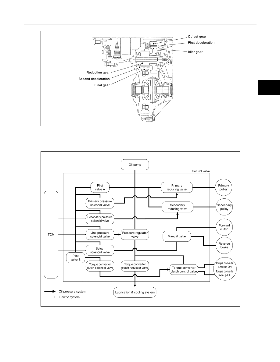
TRANSAXLE : Oil Pressure System 

INFOID:0000000010589231

Oil pressure required for operation of the transaxle transmission mechanism is generated by oil pump, oil
pressure control valve, solenoid valve, etc. 

JSDIA2427GB

JSDIA3786GB

TM-232

< SYSTEM DESCRIPTION >

[CVT: RE0F10D]

STRUCTURE AND OPERATION

TRANSAXLE : Component Description

INFOID:0000000010589232

FLUID COOLER & FLUID WARMER SYSTEM

Part name

Function

Torque converter

Increases engine torque and transmits it to the transaxle.

Oil pump

Utilizes a vane-type oil pump that is driven by the engine through the oil pump drive chain in order to 
increase efficiency of pump discharge volume in low-speed zone and optimize pump discharge volume 
in high-speed zone. Discharged oil from oil pump is transmitted to control valve. It is used as the oil of 
primary and secondary pulley operation, the oil of clutch operation, and the lubricant for each part.

Forward clutch

The forward clutch is wet and multiple plate type clutch that consists of clutch drum, piston, drive plate, 
and driven plate. It is a clutch to move the vehicle forward by activating piston hydraulically, engaging 
plates, and directly connecting sun gear and input shaft.

Reverse brake

The reverse brake is a wet multiple-plate type brake that consists of transaxle case, piston, drive plate, 
and driven plate. It is a brake to move the vehicle in reverse by activating piston hydraulically, engaging 
plates, and fixing planetary gear.

Internal gear

The internal gear is directly connected to forward clutch drum. It is a gear that moves the outer edge of 
pinion planet of planet carrier. It transmits power to move the vehicle in reverse when the planet carrier 
is fixed.

Planet carrier

Composed of a carrier, pinion planet, and pinion shaft. This gear fixes and releases the planet carrier in 
order to switch between forward and reverse driving.

Sun gear

Sun gear is a set part with planet carrier and internal gear. It transmits transmitted force to primary fixed 
sheave. It rotates in forward or reverse direction according to activation of either forward clutch or re-
verse brake.

Input shaft

The input shaft is directly connected to forward clutch drum and transmits traction force from torque con-
verter. In shaft center, there are holes for hydraulic distribution to primary pulley and hydraulic distribution 
for lockup ON/OFF.

Primary pulley

It is composed of a pair of pulleys (the groove width is changed freely in the axial direction) and the steel 
belt. The groove width changes according to wrapping radius of steel belt and pulley from low status to 
overdrive status continuously with non-step. It is controlled with the oil pressures of primary pulley and 
secondary pulley.

Secondary pulley

Steel belt

Manual shaft

When the manual shaft is in the P position, the parking rod that is linked to the manual shaft rotates the 
parking pole. When the parking pole rotates, it engages with the parking gear, fixing the parking gear. As 
a result, the secondary pulley that is integrated with the parking gear is fixed.

Parking rod

Parking pawl

Parking gear

Output gear

The deceleration gears are composed of 2 stages: primary deceleration (output gear, idler gear pair) and 
secondary deceleration (reduction gear, final gear pair). All of these gears are helical gears.

Idler gear

Reduction gear

Differential 

Torque converter regulator 
valve

Adjusts the feed pressure to the torque converter to the optimum pressure corresponding to the driving 
condition.

Pressure regulator valve

Adjusts the discharge pressure from the oil pump to the optimum pressure (line pressure) corresponding 
to the driving condition.

Torque converter clutch 
control valve

Adjusts the torque converter engage and disengage pressures.

Manual valve

Distributes the clutch operation pressure to each circuit according to the selector lever position.

Secondary reducing valve

Reduces line pressure and adjusts secondary pressure.

Primary reducing valve

Reduces line pressure and adjusts primary pressure.

Pilot valve A

Reduces line pressure and adjusts pilot pressure to the solenoid valves listed below.
• Primary pressure solenoid valve
• Secondary pressure solenoid valve
• Select solenoid valve
• Line pressure solenoid valve

Pilot valve B

Reduces pilot pressure and adjusts pilot pressure to the torque converter clutch solenoid valve.

STRUCTURE AND OPERATION

TM-233

< SYSTEM DESCRIPTION >

[CVT: RE0F10D]

C

E

F

G

H

I

J

K

L

M

A

B

TM

N

O

P

FLUID COOLER & FLUID WARMER SYSTEM : System Description

INFOID:0000000010589233

CVT FLUID COOLER SCHEMATIC

COMPONENT DESCRIPTION

CVT Oil Warmer

• The CVT oil warmer 

 is installed on the front part of transaxle

assembly.

• When engine is started while engine and CVT are cold, engine

coolant temperature rises more quickly than CVT fluid tempera-
ture. CVT oil warmer is provided with two circuits for CVT and
engine coolant respectively so that warmed engine coolant warms
CVT quickly. This helps shorten CVT warming up time, improving
fuel economy.

• A cooling effect is obtained when CVT fluid temperature is high.

Heater Thermostat

• The heater thermostat 

 is installed on the front part of transaxle

assembly.

• The heater thermostat open and close with set temperature.

CVT Fluid Cooler

• The CVT fluid cooler is installed to the vehicle front.
• CVT fluid is cooled by driving blast while driving the vehicle.

SHIFT LOCK SYSTEM

JSDIA5253GB

JSDIA5059ZZ

JSDIA5254ZZ

JSDIA5255ZZ

TM-234

< SYSTEM DESCRIPTION >

[CVT: RE0F10D]

STRUCTURE AND OPERATION

SHIFT LOCK SYSTEM : System Description

INFOID:0000000010661300

• The shift lock system prevents the select lever from being moved from “P” position to other positions due to

a driver's improper operation and prevents the occurrence of an abrupt start.

• Shift lock can be released when the following conditions are satisfied.
- Ignition switch is ON.
- Brake pedal is depressed. (Stop lamp switch is ON)

SHIFT LOCK OPERATION AT P POSITION

When brake pedal is not depressed (no selector operation allowed)

When the brake pedal is not depressed with the ignition switch ON,
the shift lock solenoid 

 is OFF (not energized) and the solenoid rod

 is extended with spring.

The connecting lock lever 

 is located at the position shown in the

figure when the solenoid rod is extended. It prevents the movement
of the detent rod 

. The selector lever cannot be shifted from the “P”

position for this reason.

When brake pedal is depressed (selector lever operation allowed)

The shift lock solenoid 

 is turned ON (energized) when the brake

pedal is depressed with the ignition switch ON. The solenoid rod 
is compressed with the electromagnetic force. The connecting lock
lever 

 rotates when the solenoid rod is compressed. Therefore, the

detent rod 

 can be moved. The selector lever can be shifted to

other positions for this reason.

FORCIBLE RELEASE OF SHIFT LOCK

• When battery voltage decreases or an electrical/mechanical mal-

function occurs in the shift lock system, the selector lever cannot
be operated in “P” position. When shift lock release rod 

 is

pressed in this state, lock lever 

 is forcibly rotated, and then it

becomes possible to release shift lock.

• To release the shift lock forcibly and shift the selector lever from “P” position to other positions, follow the

steps below.

1.

Turn ignition switch OFF.

2.

Apply parking brake.

JSDIA2817ZZ

JSDIA2818ZZ

: Shift lock solenoid

: Detent rod

JSDIA2819ZZ


Content   ..  662  663  664  665   ..