Nissan Qashqai J11. Manual - part 605


  Index      Nissan     Nissan Qashqai J11 - Service and Repair Manual


Search            


Content   ..  603  604  605  606   ..


Nissan Qashqai J11. Manual - part 605


CL-26

< UNIT REMOVAL AND INSTALLATION >

CLUTCH DISC AND CLUTCH COVER

R9M : Exploded View

INFOID:0000000010288579

CAUTION:

• If transaxle assembly is removed from the vehicle, always replace CSC (Concentric Slave Cylinder). Return CSC insert to

original position to remove transaxle assembly. Dust on clutch disc sliding parts may damage seal of CSC and may cause
clutch fluid leakage.

• Never bring any grease to the clutch disc facing, pressure plate surface and flywheel surface.

• When installing, be careful that grease applied to input shaft does not adhere to clutch disc.

• Never clean in solvent on clutch disc.

R9M : Removal and Installation

INFOID:0000000010288580

CAUTION:

If transaxle assembly is removed from the vehicle, always replace CSC (Concentric Slave Cylinder).
Return CSC insert to original position to remove transaxle assembly. Dust on clutch disc sliding parts
may damage seal of CSC and may cause clutch fluid leakage.

REMOVAL

1.

Remove transaxle assembly from the vehicle. Refer to 

TM-148, "Removal and Installation"
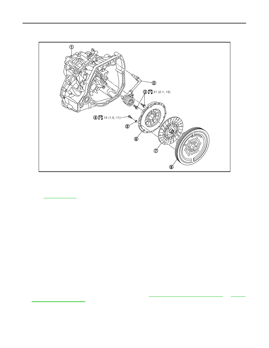
 or 

TM-88,

"Removal and Installation"

.

E1DIA0229GB

1.

Manual Transmission 

2.

Concentric slave cylinder (CSC)

3.

Bolt

4.

Clutch assembly bolt

5.

Spacer

6.

Clutch cover

7.

Clutch disc

8. 

Flywheel

Refer to 

GI-4, "Components"

 for symbols not described on the above.

NOTE:
New clutch discs are pre-greased, additional greasing is not required. If refitting used disc, apply a thin coating of grease.

CLUTCH DISC AND CLUTCH COVER

CL-27

< UNIT REMOVAL AND INSTALLATION >

C

E

F

G

H

I

J

K

L

M

A

B

CL

N

O

P

2.

Lock the flywheel using the tool [SST: — (Mot.1431)] (1).

3.

Remove three clutch cover mounting bolts at 120

°

 intervals.

4.

Replace these three bolts by the tool [SST: — (Emb.1761) (1)].

CAUTION:

Never drop clutch disc.

5.

Place the three spacers of tool [SST: — (Emb. 1761)] in contact
using the nuts. 

6.

Gradually remove the six remaining bolts.

7.

NOTE:
These instructions must be respected to prevent twisting the clutch cover:
• Unscrew and gradually remove by quarter turns the three nuts of tool [SST: — (Emb. 1761)] one by one.

8.

Remove clutch cover. 

9.

Remove clutch disc.

INSTALLATION

1.

In case of clutch cover re-used follow the procedure below :
NOTE:
The automatic compensation must be repositioned at its first point.

a.

Clean clutch disc and input shaft splines to remove grease and powder arisen from abrasion.

b.

Apply recommended grease to clutch disc and input shaft splines.

CAUTION:

Be sure to apply grease to the points specified. Otherwise, noise, poor disengagement, or damage
to the clutch may result. Excessive grease may cause slip or judder. And if it adheres to seal of
CSC, it cause clutch fluid leakage. Wipe off excess grease. Wipe off any grease oozing from the
parts.

c.

Place the base of tool (1) [SST: — (Emb.1604)] in a vice jaw.

E1BIA0774ZZ

E1BIA0776ZZ

E1BIA0779ZZ

CL-28

< UNIT REMOVAL AND INSTALLATION >

CLUTCH DISC AND CLUTCH COVER

d.

Install clutch cover onto the base plate then the ball bearing or
bronze ring (1) and the nut (2).

e.

Tighten the nut (1) fully.

f.

Fit a circlip clamp at (1).

g.

Compress the spring (1) to reprime the automatic compensa-
tion.

h.

Slacken off the nut (2) completely (spring compressed).

i.

Release the clutch cover.

j.

Remove the clutch cover from the base plate of tool [SST: —
(Emb.1604)]. 
NOTE:
Be sure that the springs are correctly compressed.

E1BIA0780ZZ

E1BIA0781ZZ

E1BIA0783ZZ

E1BIA0783ZZ

E1BIA0784ZZ

CLUTCH DISC AND CLUTCH COVER

CL-29

< UNIT REMOVAL AND INSTALLATION >

C

E

F

G

H

I

J

K

L

M

A

B

CL

N

O

P

k.

Install clutch disc on flywheel using a suitable clutch aligner (A).

l.

Install clutch cover (2)  on flywheel (1). Fit the Self Adjusting
tools (A)  using 3 of the cover bolt fixing holes.

m. Use Self Adjusting Clutch tools (A) to depress diaphram fingers

until cover body fixing flange touches flywheel. 

n.

Fit cover bolts in the 6 available holes and tighten to the speci-
fied torque. Refer to 

CL-26, "R9M : Exploded View"

 .

o.

Remove Self Adjusting Clutch tools.
Fit bolts in the 3 remaining holes and tighten to the specified
torque. Refer to 

CL-26, "R9M : Exploded View"

 .

Remove the disc alignement tool (A).

E1DIA0235ZZ

E1DIA0236ZZ

E1DIA0237ZZ

E1DIA0238ZZ

E1DIA0239ZZ


Content   ..  603  604  605  606   ..