Nissan Qashqai J11. Manual - part 595
STR-22
< DTC/CIRCUIT DIAGNOSIS >
B TERMINAL CIRCUIT
3.
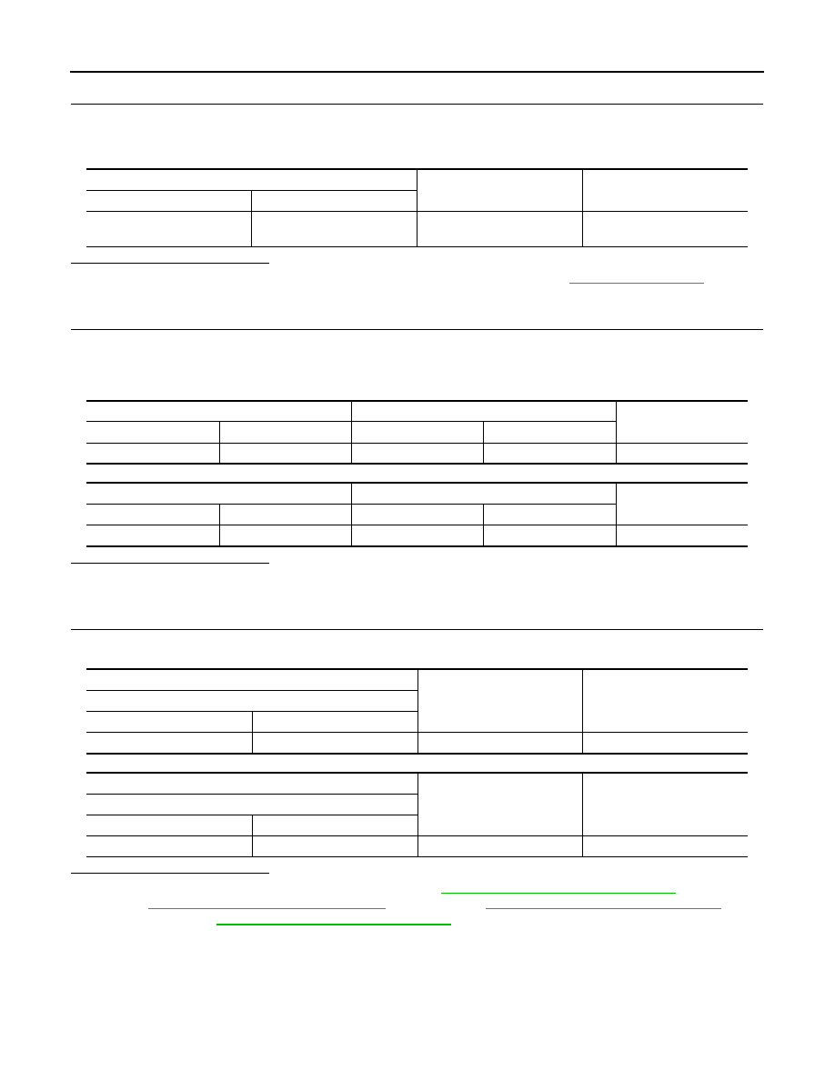
CHECK GROUND CIRCUIT STATUS (VOLTAGE DROP TEST)
1.
Shift selector lever to “P” or “N” position. (CVT models)
Keep depressing clutch pedal fully. (M/T models)
2.
Check voltage between starter motor case and battery negative terminal.
Is the inspection result normal?
YES
>> “B” terminal circuit is OK. Further inspection is necessary. Refer to
.
NO
>> Check the starter motor case and ground for poor continuity.
4.
CHECK “B” TERMINAL CIRCUIT 2
1.
Disconnect starter connector and engine restart bypass relay connector.
2.
Check continuity between starter motor harness connector and engine restart bypass relay harness con-
nector.
Except for MR16DDT engine
For MR16DDT engine
Is the inspection result normal?
YES
>> GO TO 5.
NO
>> Repair or replace harness.
5.
CHECK ENGINE RESTART BYPASS RELAY CIRCUIT
Check voltage between engine restart bypass relay harness connector and ground.
Except for MR16DDT engine
For MR16DDT engine
Is the inspection result normal?
YES
>> Replace engine restart bypass relay. Refer to
ECH-322, "Removal and Installation"
(HR engine),
ECK-402, "Removal and Installation"
EC9-413, "Removal and Installation"
(R9M
ECM-619, "Removal and Installation"
(MR16DDT engine).
NO
>> Repair or replace harness.
Terminals
Condition
Voltage (Approx.)
(+)
(–)
Starter motor case
Battery negative terminal
When the ignition switch is in
START position
Less than 0.2 V
Starter motor
Engine restart bypass relay
Continuity
Connector
Terminal
Connector
Terminal
F105
2 F147
2
Existed
Starter motor
Engine restart bypass relay
Continuity
Connector
Terminal
Connector
Terminal
E70
2 E72
2
Existed
(+)
(–)
Voltage (Approx.)
Engine restart bypass relay
Connector
Terminal
F148
3
Ground
Battery voltage
(+)
(–)
Voltage (Approx.)
Engine restart bypass relay
Connector
Terminal
E71
3
Ground
Battery voltage