Nissan Qashqai J11. Manual - part 591
STR-6
< SYSTEM DESCRIPTION >
COMPONENT PARTS
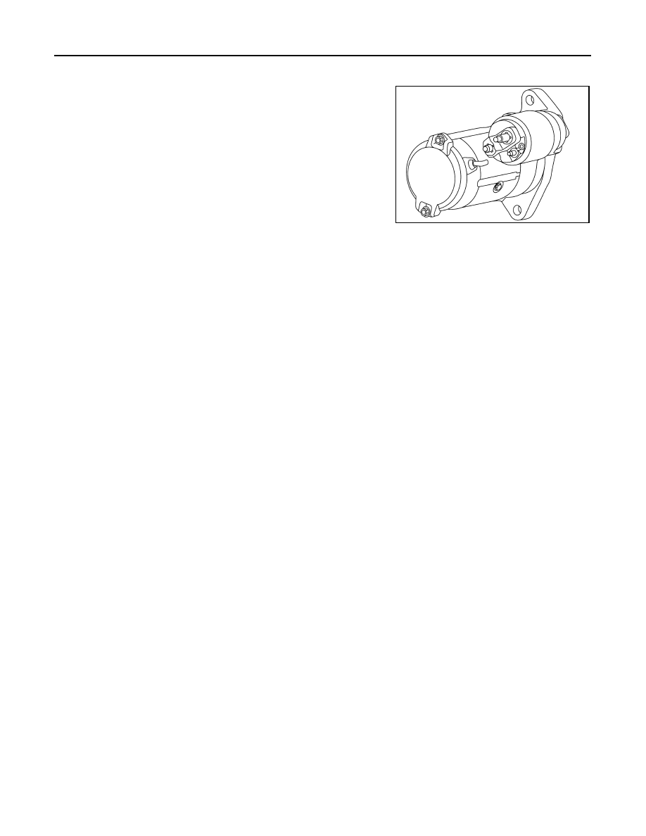
Starter motor
INFOID:0000000010430889
The starter motor plunger closes and the motor is supplied with bat-
tery power, which in turn cranks the engine, when the “S” terminal is
supplied with electric power.
JMBIA4360ZZ