Nissan Qashqai J11. Manual - part 577


  Index      Nissan     Nissan Qashqai J11 - Service and Repair Manual


Search            


Content   ..  575  576  577  578   ..


Nissan Qashqai J11. Manual - part 577


FUEL LEVEL SENSOR UNIT

FL-53

< REMOVAL AND INSTALLATION >

[R9M]

C

D

E

F

G

H

I

J

K

L

M

A

FL

N

P

O

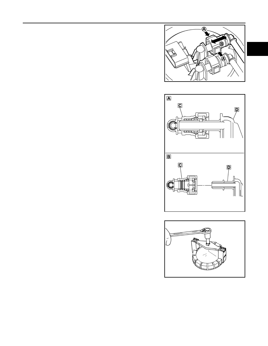
- Hold the sides of quick connector, press tabs and pull out fuel

feed tube.

- If quick connector sticks to tube of main fuel level sensor unit,

push and pull quick connectors several times until they start to
move. Then disconnect them by pulling.

CAUTION:

• Quick connector can be disconnected when the tabs are

depressed completely. Never twist it more than neces-
sary.

• Never use any tools to disconnected quick connector.
• Keep resin tube away from heat. Be especially careful

when welding near the resin tube.

• Prevent acid liquid such as battery electrolyte, etc. from

getting on resin tube.

• Never bend or twist resin tube during installation and dis-

connection.

• Never insert plug, preventing damage to O–ring in quick

connector.

• To keep the connecting portion clean and to avoid dam-

age and foreign materials, cover them completely with
plastic bags or something similar.

8.

Using lock ring wrench [SST: KV99104700], remove lock ring.
NOTE:
For reference when installing, put a matching mark on lock ring,
fuel level sensor unit and fuel tank. 

9.

Raise fuel level sensor unit.

CAUTION:

• Never bend float arm during removal. 
• Never pollute the residual fuel inside of the tank. Draw out avoiding inclination by supporting

with a cloth.

• Never cause impacts such by dropping when handling components.

10. Separate fuel tube as per the following steps to remove fuel level sensor unit.

A

: Push in tabs

B

:  Pull

E1BIA1191ZZ

A

: Connection (cross-section)

B

: Disconnection (cross-section)

C

: Quick connector

D

:  Hard  tube

E1BIA1190ZZ

PBIC0240E

FL-54

< REMOVAL AND INSTALLATION >

[R9M]

FUEL LEVEL SENSOR UNIT

• Pinch quick connector (B) square-part with your fingers, and

pull out the quick connector by hand.

• If quick connector and tube on sender unit are stuck, push

several times until they move, and pull out.
NOTE:
When separating the fuel tube, tie a diesel-resistance rope to
the tip of the fuel tube and leave the rope on the fuel tank side
to easily pull the fuel tube for installation.

• Disconnect harness connector (A).

Sub Fuel Level Sensor Assembly

1.

Remove fuel level sensor unit, fuel filter and fuel pump assembly.

2.

Use lock ring wrench [SST: KV99104700] to remove lock ring.

3.

Remove sub fuel level sensor assembly (1).

CAUTION:

• Never disassemble a fuel tube (2) from sub fuel sensor

assembly.

• Never bend float arm during removal. 
• Never pollute the residual fuel inside of the tank. Draw out

avoiding inclination by supporting with a cloth.

• Never cause impacts such by dropping when handling

components.

NOTE:
Tie a gasoline-resistance rope to a tip of the tube. Draw and
leave the rope to the fuel tank side so that the rope can be the
guide for installation.

INSTALLATION

Note the following, and install in the reverse order of removal.

Sub Fuel Level Sensor Assembly

1.

Install O-ring to fuel tank without any twist.

2.

Using the rope left on the fuel tank side at removal, run the fuel tube inside the fuel tank to install the sub
fuel level sensor assembly to the fuel tank.

CAUTION:

• Never bend float arm during installation. 

JPBIA0851ZZ

PBIC0240E

JPBIA0823ZZ

FUEL LEVEL SENSOR UNIT

FL-55

< REMOVAL AND INSTALLATION >

[R9M]

C

D

E

F

G

H

I

J

K

L

M

A

FL

N

P

O

• To install, fuel tube (1) must run to the front (

) of the vehicle to avoid the interference with the

float arm (2), as shown in the figure.

3.

Install sub fuel level sensor assembly with its matching mark (A)
aligned with fuel tank matching mark (B) as shown in the figure.

4.

Use lock ring wrench [SST: 99104700] to install lock ring as per
the following steps.

a.

Align the “ ” mark located on the rim of the lock ring (1) with the
“MAX” position of the fuel tank. Press the locking ring horizon-
tally to prevent the lock ring from tilting.
NOTE:
• Figure shows fuel level sensor unit, fuel filter and fuel pump

assembly side of fuel tank.

• For sub fuel level sensor assembly matching mark is located

on the fuel tank of the vehicle front side.

b.

After aligning the “ ” mark with “MAX” turn the lock ring counter-
clockwise until the lock ring thread engages with the tank.
Turn the lock ring roughly 540

°

 until the “ ” mark is between

"MIN" and "MAX" position.

E1BIA1189ZZ

E1BIA1135ZZ

PBIC0240E

Tightening angle

: Approximately 540

°

E1BIA1136ZZ

FL-56

< REMOVAL AND INSTALLATION >

[R9M]

FUEL LEVEL SENSOR UNIT

c.

Check that the “ ” mark of the lock ring (1) is between MIN and
MAX [i.e. within (A)].
NOTE:
• Figure shows fuel level sensor unit, fuel filter and fuel pump

assembly side of fuel tank.

• For sub fuel level sensor assembly matching mark is located

on the fuel tank of the vehicle front side.

Fuel Level Sensor Unit

1.

Temporarily install the O-ring to the fuel level sensor unit.

2.

Connect the fuel tube as per the following steps.
• Insert the quick connector (B) straight to the fuel level sensor

unit.

• Judge a good fit from connecting sound and tactile feedback.
• Pull the fuel tube by hand to check a secure fit.

3.

Connect harness connector (A).

4.

Insert the fuel level sensor unit to the fuel tank, and then install the temporarily installed O-ring (Step 1) to
the opening of the fuel tank. 

CAUTION:

• Never bend float arm during installation. 
• To install, fuel tube (1) must run to the front (

) of the vehicle to avoid the interference with the

float arm (2), as shown in the figure.

E1BIA1138ZZ

JPBIA0851ZZ

E1BIA1189ZZ


Content   ..  575  576  577  578   ..