Nissan Qashqai J11. Manual - part 576


  Index      Nissan     Nissan Qashqai J11 - Service and Repair Manual


Search            


Content   ..  574  575  576  577   ..


Nissan Qashqai J11. Manual - part 576


FUEL LEVEL SENSOR UNIT

FL-49

< REMOVAL AND INSTALLATION >

[R9M]

C

D

E

F

G

H

I

J

K

L

M

A

FL

N

P

O

4.

Open fuel filler lid and filler cap to release the pressure inside fuel tank.

5.

Remove rear seat. Refer to 

SE-35, "Removal and Installation"

.

6.

Remove inspection hole cover.

7.

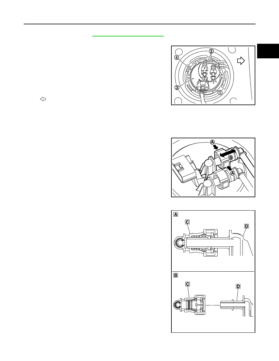
Disconnect harness connector and fuel feed tube.
NOTE:
Make sure that identification between the feed line and return
line is made to enable correct assembly during installation.

• Remove quick connector in the following procedures.
NOTE:

• The figure show the process of quick connector disconnection. Parts arround quick connector could

have a different shape compare to the figure.

- Hold the sides of quick connector, press tabs and pull out fuel

feed tube.

- If quick connector sticks to tube of main fuel level sensor unit,

push and pull quick connectors several times until they start to
move. Then disconnect them by pulling.

CAUTION:

• Quick connector can be disconnected when the tabs are

depressed completely. Never twist it more than neces-
sary.

• Never use any tools to disconnected quick connector.
• Keep resin tube away from heat. Be especially careful

when welding near the resin tube.

• Prevent acid liquid such as battery electrolyte, etc. from

getting on resin tube.

• Never bend or twist resin tube during installation and dis-

connection.

• Never insert plug, preventing damage to O–ring in quick

connector.

• To keep the connecting portion clean and to avoid dam-

age and foreign materials, cover them completely with
plastic bags or something similar.

1

: Harness connector

2

: Quick connector

3

: Fuel level sensor unit, fuel filter and fuel pump assembly

4

:  Lock  ring

: Vehicle front

E1BIA1129ZZ

A

: Push in tabs

B

:  Pull

E1BIA1191ZZ

A

: Connection (cross-section)

B

: Disconnection (cross-section)

C

: Quick connector

D

:  Hard  tube

E1BIA1190ZZ

FL-50

< REMOVAL AND INSTALLATION >

[R9M]

FUEL LEVEL SENSOR UNIT

8.

Use lock ring wrench [SST: KV101207S0] (A) to remove lock
ring.

CAUTION:

• To prevent lock ring wrench from being detached,

securely hold down spinner handle (B) by hand.

• To reduce impact caused by removal operation, use long

spinner handle [handle length: 60 cm (23.62 in) or more]
and slowly turn it counterclockwise.

9.

Remove fuel level sensor unit, fuel filter and fuel pump assembly
(1).

CAUTION:

• Never bend float arm (2) during removal.
• Never pollute the residual fuel inside of the tank. Draw out

avoiding inclination by supporting with a cloth.

• Never cause impacts such by dropping when handling

components.

INSTALLATION

Note to the following, and install in the reverse order of removal.

Fuel Level Sensor Unit

1.

Install new O-ring to fuel tank without any twist.

2.

Install the fuel gauge on the fuel tank with the fuel gauge top sur-
face (A) faced the front of the vehicle.

CAUTION:

• Never allow O-ring to drop.
• Never bend float arm during installing.

3.

Install lock ring for fuel level sensor unit, fuel filter and fuel pump assembly with lock ring wrench [SST:
KV101207S0] by turning clockwise.

CAUTION:

• Install lock ring horizontally.
• Turn the lock ring (A) until it is engaged in the fuel tank

side (B) as shown in the figure.

Quick Connector

• Connect quick connector as follows:
1.

Check the connection for damage or any foreign materials.

JSBIA1633ZZ

JPBIA3557ZZ

: Vehicle front

E1BIA1188ZZ

JPBIA3559ZZ

FUEL LEVEL SENSOR UNIT

FL-51

< REMOVAL AND INSTALLATION >

[R9M]

C

D

E

F

G

H

I

J

K

L

M

A

FL

N

P

O

2.

Align the connector with the tube, then insert the connector straight into the tube until a “click” sound is
heard.

3.

After connecting, check that the connection is secured with following procedures.
• Visually confirm that the two tabs are connected to the connector. 
• Pull (A) the tube and the connector to check that they are

securely connected.

4.

Reattach harness connector.

2WD : Inspection

INFOID:0000000010430541

INSPECTION AFTER INSTALLATION

Use the following procedure to check for fuel leaks.
1.

Turn ignition switch “ON” (with engine stopped), then check connections for leaks by applying fuel pres-
sure to fuel piping.

2.

Start engine and let it idle and make sure there are no fuel leaks at the fuel system connections.

4WD

4WD : Exploded View

INFOID:0000000010430557

JPBIA0140ZZ

JPBIA3175ZZ

FL-52

< REMOVAL AND INSTALLATION >

[R9M]

FUEL LEVEL SENSOR UNIT

Refer to 

GI-4, "Components"

 for symbol marks in the figure.

CAUTION:

Never remove or disassemble parts unless instructed as shown in the figure.

4WD : Removal and Installation

INFOID:0000000010430556

REMOVAL

Fuel Level Sensor Unit

WARNING:

Be sure to read “General Precautions” before working on the fuel system. Refer to 

FL-43, "General

Precautions"

.

1.

Release the fuel pressure from the fuel lines. Refer to 

ECK-153, "Work Procedure"

.

2.

Check fuel level on a level ground. If the fuel level is at 1/2 or higher, drain enough fuel so that the level on
the fuel gauge is at half or below.
• This is to prevent overflow of fuel from the tank when the  fuel level sensor unit, fuel filter and fuel pump

assembly is removed 

• In the event of malfunction in fuel pump, insert a hose measuring less than 20mm (0.79 in) in diameter

into fuel filler tube through fuel filler opening to draw fuel from filler tube.

- Disconnect fuel filler hose from fuel filler tube. Refer to 

FL-10, "Exploded View"

- Insert hose into fuel tank through fuel filler hose to draw fuel from fuel tank.

3.

Disconnect batterie cable from negative terminal.

4.

Open fuel filler lid and filler cap to release the pressure inside fuel tank.

5.

Remove rear seat. Refer to 

SE-35, "Removal and Installation"

.

6.

Remove inspection hole cover.
• Using a screwdriver, remove it by turning clips clockwise by 90 degrees.

7.

Disconnect harness connector and quick connectors (A).
NOTE:
Make sure that identification between the feed line and return
line is made to enable correct assembly during installation.

• Remove quick connector in the following procedures.
NOTE:

• The figure show the process of quick connector disconnection. Parts arround quick connector could

have a different shape compare to the figure.

1.

Lock ring

2.

Fuel level sensor unit

3.

O-ring

4.

Sub fuel level sensor unit

A.

To fuel tank

B.

Tightening must be done following the Installation procedure. Refer to 

FL-52, "4WD : Removal and Installation"

.

: Vehicle front

Guideline

: Draw approximately 32 liters (7 Imp gal) from a full-tank con-
dition.

1

: Fuel tube (return side)

2

: Fuel tube (feed side)

JPBIA0852ZZ


Content   ..  574  575  576  577   ..