Nissan Qashqai J11. Manual - part 573


  Index      Nissan     Nissan Qashqai J11 - Service and Repair Manual


Search            


Content   ..  571  572  573  574   ..


Nissan Qashqai J11. Manual - part 573


FUEL LEVEL SENSOR UNIT, FUEL FILTER AND FUEL PUMP ASSEMBLY

FL-37

< REMOVAL AND INSTALLATION >

[K9K]

C

D

E

F

G

H

I

J

K

L

M

A

FL

N

P

O

8.

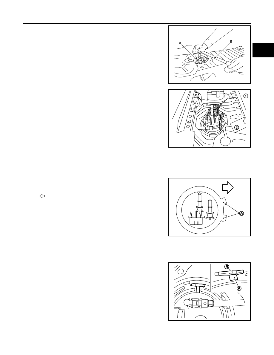
Use lock ring wrench [SST: KV101207S0] (A) to remove lock
ring.

CAUTION:

• To prevent lock ring wrench from being detached,

securely hold down spinner handle (B) by hand.

• To reduce impact caused by removal operation, use long

spinner handle [handle length: 60 cm (23.62 in) or more]
and slowly turn it counterclockwise.

9.

Remove fuel level sensor unit, fuel filter and fuel pump assembly
(1).

CAUTION:

• Never bend float arm (2) during removal.
• Never pollute the residual fuel inside of the tank. Draw out

avoiding inclination by supporting with a cloth.

• Never cause impacts such by dropping when handling

components.

INSTALLATION

Note to the following, and install in the reverse order of removal.

Fuel Level Sensor Unit

1.

Install new O-ring to fuel tank without any twist.

2.

Install the fuel gauge on the fuel tank with the fuel gauge top sur-
face (A) faced the front of the vehicle.

CAUTION:

• Never allow O-ring to drop.
• Never bend float arm during installing.

3.

Install lock ring for fuel level sensor unit, fuel filter and fuel pump assembly with lock ring wrench [SST:
KV101207S0] by turning clockwise.

CAUTION:

• Install lock ring horizontally.
• Turn the lock ring (A) until it is engaged in the fuel tank

side (B) as shown in the figure.

Quick Connector

• Connect quick connector as follows:
1.

Check the connection for damage or any foreign materials.

JSBIA1633ZZ

JPBIA3557ZZ

: Vehicle front

E1BIA1188ZZ

JPBIA3559ZZ

FL-38

< REMOVAL AND INSTALLATION >

[K9K]

FUEL LEVEL SENSOR UNIT, FUEL FILTER AND FUEL PUMP ASSEMBLY

2.

Align the connector with the tube, then insert the connector straight into the tube until a “click” sound is
heard.

3.

After connecting, check that the connection is secured with following procedures.
• Visually confirm that the two tabs are connected to the connector. 
• Pull (A) the tube and the connector to check that they are

securely connected.

4.

Reattach harness connector.

Inspection

INFOID:0000000010430519

INSPECTION AFTER INSTALLATION

Use the following procedure to check for fuel leaks.
1.

Turn ignition switch “ON” (with engine stopped), then check connections for leaks by applying fuel pres-
sure to fuel piping.

2.

Start engine and let it idle and make sure there are no fuel leaks at the fuel system connections.

JPBIA0140ZZ

FUEL TANK

FL-39

< REMOVAL AND INSTALLATION >

[K9K]

C

D

E

F

G

H

I

J

K

L

M

A

FL

N

P

O

FUEL TANK

Exploded View

INFOID:0000000010419002

Refer to 

GI-4, "Components"

 for symbol marks in the figure.

Removal and Installation

INFOID:0000000010430532

REMOVAL

WARNING:

Be sure to read “General Precautions” when working on the fuel system. Refer to 

FL-30, "General Pre-

cautions"

.

1.

Perform the steps 1 to 7 of “REMOVAL” in “ FUEL LEVEL SENSOR UNIT, FUEL FILTER AND FUEL
PUMP ASSEMBLY”. Refer to 

FL-6, "Removal and Installation"

.

2.

Drain fuel from fuel tank if necessary. Refer to 

FL-6, "Removal and Installation"

.

CAUTION:

• Fuel tank will become unstable whilst removing. Fuel should be drained from tank prior to

removal to reduce this effect.

• Situate vehicle on a flat and solid surface.

3.

Remove main muffler. Refer to 

EX-6, "Exploded View"

.

4.

Remove vent hose from filler tube.

5.

Remove fuel filler hose from fuel tank.

CAUTION:

1.

Fuel filler cap

2.

Grommet

3.

Fuel filler tube

4.

Clamp

5.

Fuel filler hose

6.

Clamp

7.

Clamp

8.

Vent hose

9.

Evap hose

10. Fuel tank 

11.

Fuel tank band (RH)

12. Fuel tank band (LH)

E1BIA1127GB

FL-40

< REMOVAL AND INSTALLATION >

[K9K]

FUEL TANK

• Do not remove fuel filler hose from fuel filler tube to prevent interference with suspension when

installing.

• If removal of fuel filler hose from fuel filler tube is necessary use mating marks to ensure correct

orientation. 

6.

Disconnect EVAP hose.
• Remove quick connector in the following procedures.
- Hold the sides of quick connector, press tabs and disconnect EVAP hose.
- If quick connector sticks to tube, push and pull quick connectors several times until they start to move.

Then disconnect them by pulling.

CAUTION:

• Quick connector can be disconnected when the tabs (1)

are depressed completely. Never twist it more than neces-
sary.

• Never use any tools to disconnected quick connector.

• Keep resin tube away from heat. Be especially careful

when welding near the resin tube.

• Prevent acid liquid such as battery electrolyte, etc. from

getting on resin tube.

• Never bend or twist resin tube during installation and dis-

connection.

• Never insert plug, preventing damage to O–ring in quick

connector.

• To keep the connecting portion clean and to avoid dam-

age and foreign materials, cover them completely with
plastic bags or something similar.

E1BIA1192ZZ

A

: Connection (cross-section)

B

: Disconnection (cross-section)

C

: Quick connector

D

: Hard tube

E1BIA1190ZZ


Content   ..  571  572  573  574   ..