Nissan Qashqai J11. Manual - part 572
FUEL FILTER
FL-33
< PERIODIC MAINTENANCE >
[K9K]
C
D
E
F
G
H
I
J
K
L
M
A
FL
N
P
O
FUEL FILTER
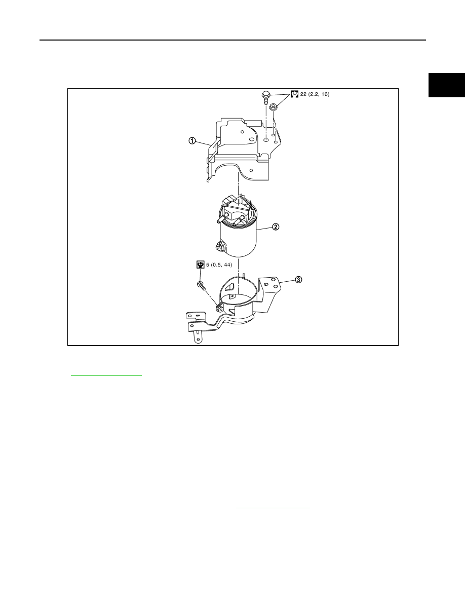
Exploded View
INFOID:0000000010428755
for symbol marks in the figure.
Removal and Installation
INFOID:0000000010428756
REMOVAL
1.
Remove fuel protector.
2.
Disconnect quick connectors, and remove fuel hoses.
CAUTION:
Never splash fuel during removal. If fuel is splashed, immediately wipe it off.
3.
Disconnect fuel filter connector.
4.
Remove fuel filter.
INSTALLATION
1.
Note the following, and install in the reverse order of removal.
• After installation, bleed air from fuel line. Refer to
CAUTION:
Never bend or twist the fuel tube during installation and removal.
1.
Fuel filter protector
2.
Fuel filter
3.
Fuel filter bracket
E1BIA1184GB