Nissan Qashqai J11. Manual - part 566


  Index      Nissan     Nissan Qashqai J11 - Service and Repair Manual


Search            


Content   ..  564  565  566  567   ..


Nissan Qashqai J11. Manual - part 566


FUEL LEVEL SENSOR UNIT, FUEL FILTER AND FUEL PUMP ASSEMBLY

FL-9

< REMOVAL AND INSTALLATION >

[HRA2DDT]

C

D

E

F

G

H

I

J

K

L

M

A

FL

N

P

O

2.

Align the connector with the tube, then insert the connector straight into the tube until a “click” sound is
heard.

3.

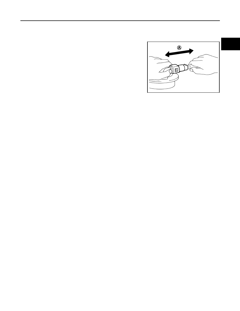
After connecting, check that the connection is secured with following procedures.
• Visually confirm that the two tabs are connected to the connector. 
• Pull (A) the tube and the connector to check that they are

securely connected.

4.

Reattach harness connector.

Inspection

INFOID:0000000010418981

INSPECTION AFTER INSTALLATION

Use the following procedure to check for fuel leaks.
1.

Turn ignition switch “ON” (with engine stopped), then check connections for leaks by applying fuel pres-
sure to fuel piping.

2.

Start engine and let it idle and make sure there are no fuel leaks at the fuel system connections.

JPBIA0140ZZ

FL-10

< REMOVAL AND INSTALLATION >

[HRA2DDT]

FUEL TANK

FUEL TANK

Exploded View

INFOID:0000000010418985

Refer to 

GI-4, "Components"

 for symbol marks in the figure.

Removal and Installation

INFOID:0000000010418986

REMOVAL

WARNING:

Be sure to read “General Precautions” when working on the fuel system. Refer to 

FL-3, "General Pre-

cautions"

.

1.

Perform the steps 1 to 7 of “REMOVAL” in “ FUEL LEVEL SENSOR UNIT, FUEL FILTER AND FUEL
PUMP ASSEMBLY”. Refer to 

FL-6, "Removal and Installation"

.

2.

Drain fuel from fuel tank if necessary. Refer to 

FL-6, "Removal and Installation"

.

CAUTION:

• Fuel tank will become unstable whilst removing. Fuel should be drained from tank prior to

removal to reduce this effect.

• Situate vehicle on a flat and solid surface.

3.

Remove main muffler. Refer to 

EX-6, "Exploded View"

.

4.

Remove vent hose from filler tube.

1.

Fuel filler cap

2.

Grommet

3.

Fuel filler tube

4.

Clamp

5.

Fuel filler hose

6.

Clamp

7.

Clamp

8.

Vent hose

9.

EVAP hose

10. Fuel tank

11.

Fuel tank band (RH)

12. Fuel tank band (LH)

E1BIA1121GB

FUEL TANK

FL-11

< REMOVAL AND INSTALLATION >

[HRA2DDT]

C

D

E

F

G

H

I

J

K

L

M

A

FL

N

P

O

5.

Remove fuel filler hose from fuel tank.

CAUTION:

• Do not remove fuel filler hose from fuel filler tube to prevent interference with suspension when

installing.

• If removal of fuel filler hose from fuel filler tube is necessary use mating marks to ensure correct

orientation. 

6.

Disconnect EVAP hose.
• Remove quick connector in the following procedures.
- Hold the sides of quick connector, press tabs and disconnect EVAP hose.
- If quick connector sticks to tube, push and pull quick connectors several times until they start to move.

Then disconnect them by pulling.

CAUTION:

• Quick connector can be disconnected when the tabs (1)

are depressed completely. Never twist it more than neces-
sary.

• Never use any tools to disconnected quick connector.

• Keep resin tube away from heat. Be especially careful

when welding near the resin tube.

• Prevent acid liquid such as battery electrolyte, etc. from

getting on resin tube.

• Never bend or twist resin tube during installation and dis-

connection.

• Never insert plug, preventing damage to O–ring in quick

connector.

• To keep the connecting portion clean and to avoid dam-

age and foreign materials, cover them completely with
plastic bags or something similar.

E1BIA1192ZZ

A

: Connection (cross-section)

B

: Disconnection (cross-section)

C

: Quick connector

D

:  Hard  tube

E1BIA1190ZZ

FL-12

< REMOVAL AND INSTALLATION >

[HRA2DDT]

FUEL TANK

7.

Support center of fuel tank (1) with transmission jack (A) and
piece of wood (B).

CAUTION:

• Make sure the tank bottom surface is supported well

enough to prevent an unstable condition when lowering
the tank.

• Make sure to hold it securely as tank surface may not be

flat.

8.

Remove fuel tank band (RH and LH).

9.

Lower transmission jack carefully to remove fuel tank while holding it by hand. 

CAUTION:

Make sure to avoid any interference with surrounding component that may cause damage.

INSTALLATION

Note the following, and install in the reverse order of removal.

CAUTION:

• Make sure hose clamps and hoses clips are not secured on top of the filler tube bulges.
• Make sure all quick connectors and their mating part are free of foreign matter, check for damage.
• Ensure the tank bands are correctly assembled as per their identification marks "L" and "R". 
• Make sure that the torques of the mounting bolts are correct as per exploded view. Refer to 

FL-10,

"Exploded View"

.

• Make sure that when installing the connectors, the confirmation click sound is heard. Pull back on

the connector to ensure proper engagement.

Fuel Filler Hose 

• Insert fuel filler hose to the length below.

• Be sure hose clamp is not placed on swelled area of fuel filler tube.
• Tighten fuel filler hose clamp so that the remaining length of screw thread becomes to the following.

EVAP Hose 

1.

Check connections for damage or foreign material.

2.

Align the matching side connection part with the center of shaft,
and insert connector straight until it clicks.

3.

After connecting, pull out quick connector and centralized under-
floor piping by hand. Make sure connections are secure.

Inspection

INFOID:0000000010418987

INSPECTION AFTER INSTALLATION

Use the following procedure to check for fuel leaks.
1.

Turn ignition switch “ON” (with engine stopped), and check connections for leakage by applying fuel pres-
sure to fuel piping.

PBIC3792E

: 35 mm (1.38 in)

Fuel filler tube side

: 7 - 11 mm (0.28 - 0.43 in)

Fuel tank side

: 5 - 9 mm (0.20 - 0.35 in) 

PBIC1653E


Content   ..  564  565  566  567   ..