Nissan Qashqai J11. Manual - part 431
ECK-284
< DTC/CIRCUIT DIAGNOSIS >
[K9K]
P0697 SENSOR POWER SUPPLY
P0697 SENSOR POWER SUPPLY
DTC Logic
INFOID:0000000010289894
DTC DETECTION LOGIC
DTC CONFIRMATION PROCEDURE
1.
PRECONDITIONING
If DTC Confirmation Procedure has been previously conducted, always turn ignition switch OFF and wait at
least 1 minute before conducting the next test.
>> GO TO 2.
2.
PERFORM DTC CONFIRMATION PROCEDURE
1.
Turn ignition switch ON and wait at least 1 second.
2.
Check DTC.
Is DTC detected?
YES
>> Proceed to
ECK-284, "Diagnosis Procedure"
NO
>> INSPECTION END
Diagnosis Procedure
INFOID:0000000010289895
1.
CHECK SENSOR POWER SUPPLY
1.
Turn ignition switch OFF.
2.
Disconnect fuel rail pressure (FRP) sensor harness connector.
3.
Turn ignition switch ON.
4.
Check the voltage between FRP sensor harness connector and ground.
Is the inspection result normal?
YES
>> Check intermittent incident. Refer to
GI-41, "Intermittent Incident"
.
NO
>> GO TO 2.
2.
CHECK SENSOR POWER SUPPLY CIRCUITS
1.
Turn ignition switch OFF.
2.
Disconnect ECM harness connector.
3.
Check harness for short to power and short to ground, between the following terminals.
Is the inspection result normal?
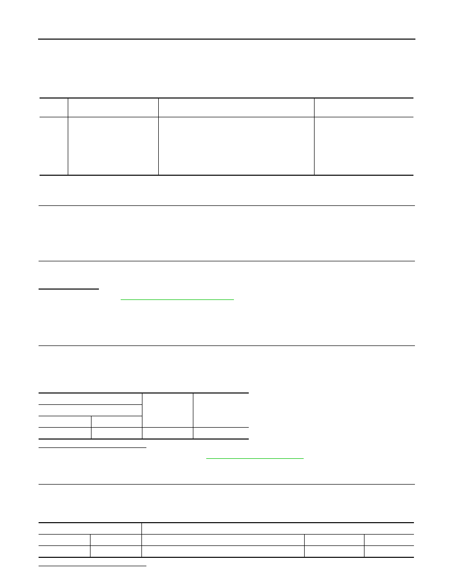
DTC
No.
CONSULT screen terms
(Trouble diagnosis content)
DTC detecting condition
Possible cause
P0697
SEN SUPPLY N-3 VOL
(Sensor reference voltage “C”
circuit/open)
• 1.DEF: VOLTAGE TOO
LOW
• 2.DEF: VOLTAGE TOO
HIGH
• A voltage of sensor power supply is more than 5.4 V.
• A voltage of sensor power supply is less than 4.6 V.
• Harness or connectors
• Fuel rail pressure sensor
+
−
Voltage
(Approx.)
FRP sensor
Connectors
Terminal
F40
3
Ground
5 V
ECM
Sensor
Connector
Terminal
Name
Connector
Terminal
F80
45
Fuel rail pressure sensor
F40
3