Nissan Qashqai J11. Manual - part 319


  Index      Nissan     Nissan Qashqai J11 - Service and Repair Manual


Search            


Content   ..  317  318  319  320   ..


Nissan Qashqai J11. Manual - part 319


P0300, P0301, P0302, P0303, P0304 MISFIRE

ECM-253

< DTC/CIRCUIT DIAGNOSIS >

[MR20DD]

C

D

E

F

G

H

I

J

K

L

M

A

ECM

N

P

O

2.

Listen to each fuel injector operation.

Is the inspection result normal?

YES

>> GO TO 5.

NO

>>  Perform trouble diagnosis for fuel injector, refer to 

ECM-

372, "Diagnosis Procedure"

.

5.

CHECK FUNCTION OF IGNITION COIL-1

CAUTION:

Perform the following procedure in a place with no combustible objects and good ventilation.
1.

Turn ignition switch OFF.

2.

Remove fuel pump fuse in IPDM E/R to release fuel pressure.
NOTE:
Do not use CONSULT to release fuel pressure, or fuel pressure applies again during the following proce-
dure.

3.

Start engine.

4.

After engine stalls, crank it 2 or 3 times to release all fuel pressure.

5.

Turn ignition switch OFF.

6.

Remove all ignition coil harness connectors to avoid the electrical discharge from the ignition coils.

7.

Remove ignition coil and spark plug of the cylinder to be checked. Refer to 

EM-170, "Removal and Instal-

lation"

.

8.

Crank engine for 5 seconds or more to remove combustion gas in the cylinder.

9.

Connect spark plug and harness connector to ignition coil.

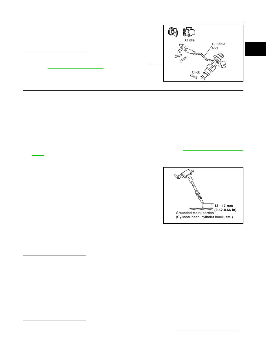
10. Fix ignition coil using a rope etc. with gap of 13 - 17 mm (0.52 -

0.66 in) between the edge of the spark plug and grounded metal
portion as shown in the figure.

11. Crank engine for approximately 3 seconds, and check whether

spark is generated between the spark plug and the grounded
metal portion.

CAUTION:

• Never place the spark plug and the ignition coil within 50

cm (19.7 in) each other. Be careful not to get an electrical
shock while checking, because the electrical discharge voltage becomes 20 kV or more.

• It might damage the ignition coil if the gap of more than 17 mm (0.66 in) is made.
NOTE:
When the gap is less than 13 mm (0.52 in), a spark might be generated even if the coil is malfunctioning.

Is the inspection result normal?

YES

>> GO TO 9.

NO

>> GO TO 6.

6.

CHECK FUNCTION OF IGNITION COIL-2

1.

Turn ignition switch OFF.

2.

Disconnect spark plug and connect a non-malfunctioning spark plug.

3.

Crank engine for approximately 3 seconds, and recheck whether spark is generated between the spark
plug and the grounded metal portion.

Is the inspection result normal?

YES

>> GO TO 7.

NO

>> Check ignition coil, power transistor and their circuits. Refer to 

ECM-385, "Diagnosis Procedure"

.

Clicking sound should 
be heard.

PBIB3332E

Spark should be gener-
ated.

JMBIA0066GB

Spark should be gener-
ated.

ECM-254

< DTC/CIRCUIT DIAGNOSIS >

[MR20DD]

P0300, P0301, P0302, P0303, P0304 MISFIRE

7.

CHECK SPARK PLUG

Check the initial spark plug for fouling, etc.
Is the inspection result normal?

YES

>> Replace spark plug(s) with standard type one(s). Refer

to 

EM-170, "Exploded View"

.

NO

>> Repair or clean spark plug. Then GO TO 8.

8.

CHECK FUNCTION OF IGNITION COIL-3

1.

Reconnect the initial spark plugs.

2.

Crank engine for approximately 3 seconds, and recheck whether spark is generated between the spark
plug and the grounded portion.

Is the inspection result normal?

YES

>> INSPECTION END

NO

>> Replace spark plug(s) with standard type one(s). Refer to 

EM-170, "Exploded View"

.

9.

CHECK COMPRESSION PRESSURE

Check compression pressure. Refer to 

EM-136, "Inspection"

.

Is the inspection result normal?

YES

>> GO TO 10.

NO

>> Check pistons, piston rings, valves, valve seats and cylinder head gaskets.

10.

CHECK FUEL PRESSURE

1.

Install all removed parts.

2.

Release fuel pressure. Refer to 

ECM-135, "Work Procedure"

.

3.

Set a fuel pressure meter and check fuel pressure. Refer to 

ECM-135, "Work Procedure"

.

Is the inspection result normal?

YES

>> GO TO 12.

NO

>> GO TO 11.

11.

DETECT MALFUNCTIONING PART

Check fuel hoses and fuel tubes for clogging.
Is the inspection result normal?

YES

>> Replace “fuel filter and fuel pump assembly”. Refer to 

FL-19, "Removal and Installation"

.

NO

>> Repair or replace malfunctioning part.

12.

CHECK IDLE SPEED AND IGNITION TIMING

Check idle speed and ignition timing.
Idle speed: For procedure, refer to 

ECM-412, "Inspection"

, for specification, refer to 

ECM-417, "Idle Speed"

.

Ignition timing: For procedure, refer to 

ECM-413, "Inspection"

, for specification, refer to 

ECM-417, "Ignition

Timing"

.

Is the inspection result normal?

YES

>> GO TO 13.

NO

>> Perform basic inspection. Refer to 

ECM-132, "Work Procedure"

.

13.

CHECK A/F SENSOR 1 INPUT SIGNAL CIRCUIT

1.

Turn ignition switch OFF.

SEF156I

Spark should be generated.

At idle: Approx. 500 kPa (5.0 bar, 5.1 kg/cm

2

, 73 psi)

P0300, P0301, P0302, P0303, P0304 MISFIRE

ECM-255

< DTC/CIRCUIT DIAGNOSIS >

[MR20DD]

C

D

E

F

G

H

I

J

K

L

M

A

ECM

N

P

O

2.

Disconnect corresponding A/F sensor 1 harness connector.

3.

Disconnect ECM harness connector.

4.

Check the continuity between A/F sensor 1 harness connector and ECM harness connector.

5.

Check the continuity between A/F sensor 1 harness connector and ground, or ECM harness connector
and ground.

6.

Also check harness for short to ground and short to power.

Is the inspection result normal?

YES

>> GO TO 14.

NO

>> Repair or replace malfunctioning part.

14.

CHECK A/F SENSOR 1 HEATER

Refer to 

ECM-165, "Component Inspection"

.

Is the inspection result normal?

YES

>> GO TO 15.

NO

>> Replace malfunctioning A/F sensor 1. Refer to 

EM-153, "Exploded View"

.

15.

CHECK MASS AIR FLOW SENSOR OUTPUT VOLTAGE

WITH CONSULT

1.

Install all removed parts.

2.

Start engine and warm it up to normal operating temperature.

3.

Select “MAS A/F SE-B1” in “DATA MONITOR” mode with CONSULT and check the indication under the
following condition.

*: Check for linear voltage rise in response to increase of engine speed.

WITHOUT CONSULT

1.

Install all removed parts.

2.

Start engine and warm it up to normal operating temperature.

3.

Check the voltage between ECM harness connector terminals.

+

Continuity

A/F sensor 1

ECM

Connector

Terminal

Connector

Terminal

F74

1

F16

64

Existed

2

72

+

Ground

Continuity

A/F sensor 1

Connector

Terminal

F74

1

Ground

Not existed

2

+

Ground

Continuity

ECM

Connector

Terminal

F16

64

Ground

Not existed

72

Monitor item

Condition

Indication

MAS A/F SE-B1

Ignition switch ON (Engine stopped.)

Approx. 0.4 V

Idle (Engine is warmed-up to normal op-
erating temperature.)

0.7 - 1.2 V

Idle to about 4,000 rpm

0.7 - 1.2 V 

 2.4 V*

ECM-256

< DTC/CIRCUIT DIAGNOSIS >

[MR20DD]

P0300, P0301, P0302, P0303, P0304 MISFIRE

*: Check for linear voltage rise in response to increase of engine speed.

Is the inspection result normal?

YES

>> GO TO 16.

NO

>> Check connectors for rusted terminals or loose connections in the mass air flow sensor circuit or

ground. Refer to 

ECM-180, "Diagnosis Procedure"

.

16.

CHECK SYMPTOM MATRIX CHART

Check items on the rough idle symptom in 

ECM-407, "Symptom Table"

.

Is the inspection result normal?

YES

>> GO TO 17.

NO

>> Repair or replace malfunctioning part.

17.

ERASE THE 1ST TRIP DTC

Some tests may cause a 1st trip DTC to be set.
Erase the 1st trip DTC from the ECM memory after performing the tests. Refer to 

ECM-65, "CONSULT Func-

tion"

.

>> INSPECTION END

ECM

Condition

Voltage

Connector

+

Terminal

Terminal

F15

28

(Mass air flow sensor 

signal)

20

(sensor 

ground)

Ignition switch ON (Engine stopped.)

Approx. 0.4 V

Idle (Engine is warmed-up to normal 
operating temperature.)

0.7 - 1.2 V

Idle to about 4,000 rpm

0.7 - 1.2 V 

 2.4 V*


Content   ..  317  318  319  320   ..