Nissan Qashqai J11. Manual - part 269
SYSTEM
ECM-53
< SYSTEM DESCRIPTION >
[MR20DD]
C
D
E
F
G
H
I
J
K
L
M
A
ECM
N
P
O
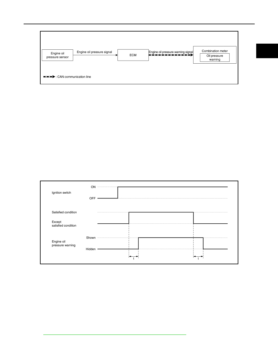
SYSTEM DIAGRAM
SIGNAL PATH
• ECM reads the resistance value of an engine oil pressure sensor and transmits the engine oil pressure
warning signal to combination meter via CAN communication.
• The information display (on combination meter) is SHOWN/HIDDEN the engine oil pressure warning,
according to the engine oil pressure sensor signal received from ECM.
LIGHTING CONDITION
When all of the following conditions are satisfied:
• Ignition switch: ON
• Engine running
• Engine oil pressure is less than the specified value.
SHUTOFF CONDITION
• Ignition switch: OFF
• Engine stop
• Engine oil pressure is the specified value or more.
TIMING CHART
CAN COMMUNICATION
CAN COMMUNICATION : System Description
INFOID:0000000010702837
CAN (Controller Area Network) is a serial communication line for real time application. It is an on-vehicle mul-
tiplex communication line with high data communication speed and excellent error detection ability. Many elec-
tronic control units are equipped onto a vehicle, and each control unit shares information and links with other
control units during operation (not independent). In CAN communication, control units are connected with 2
communication lines (CAN H line, CAN L line) allowing a high rate of information transmission with less wiring.
Each control unit transmits/receives data but selectively reads required data only.
Refer to
LAN-15, "CAN COMMUNICATION SYSTEM : System Description"
, about CAN communication for
detail.
JSBIA3494GB
JSBIA3700GB
t
: 100 ms