Content .. 2228 2229 2230 2231 ..
Nissan Qashqai J11. Manual - part 2230
DAS-334
< ECU DIAGNOSIS INFORMATION >
[PARK ASSIST]
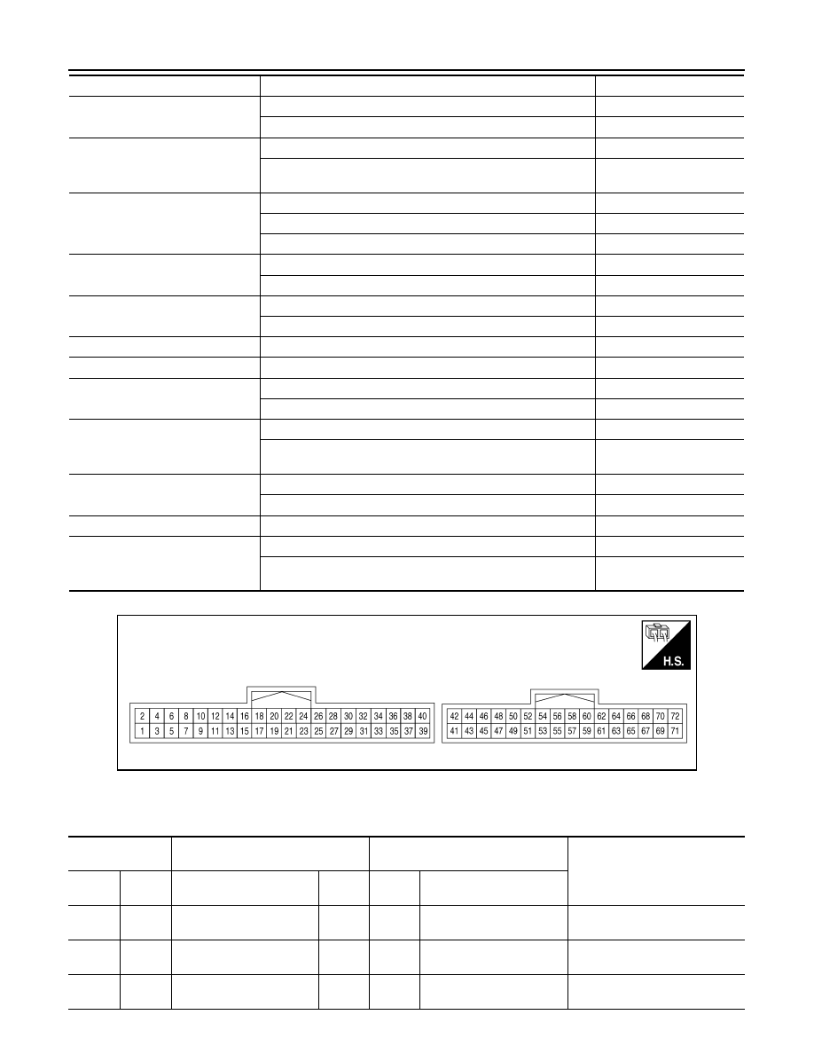
AROUND VIEW MONITOR CONTROL UNIT
TERMINAL LAYOUT
PHYSICAL VALUES
With Pump Control Unit
PA CAMERA COMM STATUS
Passenger side camera serial status is OK
OK
Passenger side camera serial status is not OK
NG
PA-SIDE CAMERA COMM LINE
Passenger side camera serial communication signal is received
OK
Passenger side camera serial communication signal is not re-
ceived
NG
TURN SIGNAL
Turn signal left is received
Left
Turn signal neutral is received
N
Turn signal right is received
Right
ITS SW 1
ITS switch is pressed
On
ITS switch is not pressed
Off
ITS SW 1 IND
Indicator of ITS switch is lighting
On
Indicator of ITS switch is not lighting
Off
ITS SW 2
For this vehicle, the displaying is fixed
No SET
ITS SW 2 IND
For this vehicle, the displaying is fixed
Off
PUMP COMM STATUS
Pump communication signal is received
On
Pump communication signal is not received
Off
VEHICLE SPEED
Vehicle stopped
0 km/h
Driving
Almost same reading as
speedometer
IDLE STOP STATUS
Stop/start system operates
On
Stop/start system not operates
Off
TRAILER HITCH SW
For this vehicle, the displaying is fixed
Off
STEERING ANGLE
The steering wheel is not steered
Approx. 0 deg
The steering wheel is steered
Displays steering angle
(deg)
Monitor Item
Condition
Value/Status
AWNIA3349ZZ
Terminal
(Wire color)
Description
Condition
Reference value
(Approx.)
+
–
Signal name
Input/
Output
Ignition
switch
Operation
1
(B)
Ground
Ground
—
ON
—
0 V
2
(Y)
Ground
Battery power supply
Input
OFF
—
Battery voltage
3
(SB)
Ground
Ignition signal
Input
ON
—
Battery voltage