Nissan Qashqai J11. Manual - part 214
ECH-154
< DTC/CIRCUIT DIAGNOSIS >
[HRA2DDT]
P0016 CKP - CMP CORRELATION
Is the inspection result normal?
YES
>> GO TO 5.
NO
>> Replace signal plate with flywheel.
5.
CHECK TIMING CHAIN
Check timing chain. Refer to
EM-59, "Removal and Installation"
Is the inspection result normal?
YES
>> Check intermittent incident. Refer to
GI-41, "Intermittent Incident"
.
NO
>> Replace timing chain. Refer to
EM-59, "Removal and Installation"
Component Inspection (Crankshaft Position Sensor)
INFOID:0000000010499957
1.
CHECK CRANKSHAFT POSITION SENSOR
1.
Turn ignition switch OFF.
2.
Disconnect crankshaft position (CKP) sensor harness connector.
3.
Check the resistance between CKP sensor terminals.
Is the inspection result normal?
YES
>> INSPECTION END
NO
>> Replace CKP sensor.
Component Inspection (Camshaft Position Sensor)
INFOID:0000000010499958
1.
CHECK CAMSHAFT POSITION SENSOR
1.
Turn ignition switch OFF.
2.
Disconnect camshaft position (CMP) sensor harness connector.
3.
Check the resistance between CMP sensor terminals.
Is the inspection result normal?
YES
>> INSPECTION END
NO
>> Replace CMP sensor.
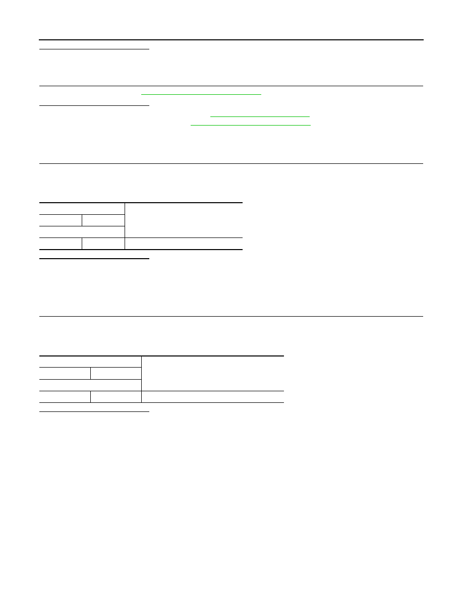
CKP sensor
Resistance
+
−
Terminal
1
2
520 - 860
Ω
CMP sensor
Resistance
+
−
Terminal
1
2
More than 100 k
Ω