Content .. 2114 2115 2116 2117 ..
Nissan Qashqai J11. Manual - part 2116
AV
AROUND VIEW MONITOR CONTROL UNIT
AV-153
< ECU DIAGNOSIS INFORMATION >
[NAVIGATION]
C
D
E
F
G
H
I
J
K
L
M
B
A
O
P
Terminal
(Wire color)
Description
Condition
Reference value
(Approx.)
+
–
Signal name
Input/
Output
Ignition
switch
Operation
1
(B)
Ground
Ground
—
ON
—
0 V
2
(Y)
Ground
Battery power supply
Input
OFF
—
Battery voltage
4
(SB)
Ground
Ignition signal
Input
ON
—
Battery voltage
10
(R)
—
CAN (L)
Input/
Output
— —
—
12
(L)
—
CAN (H)
Input/
Output
— —
—
23
(Shield)
—
Camera image signal
shield
—
—
—
—
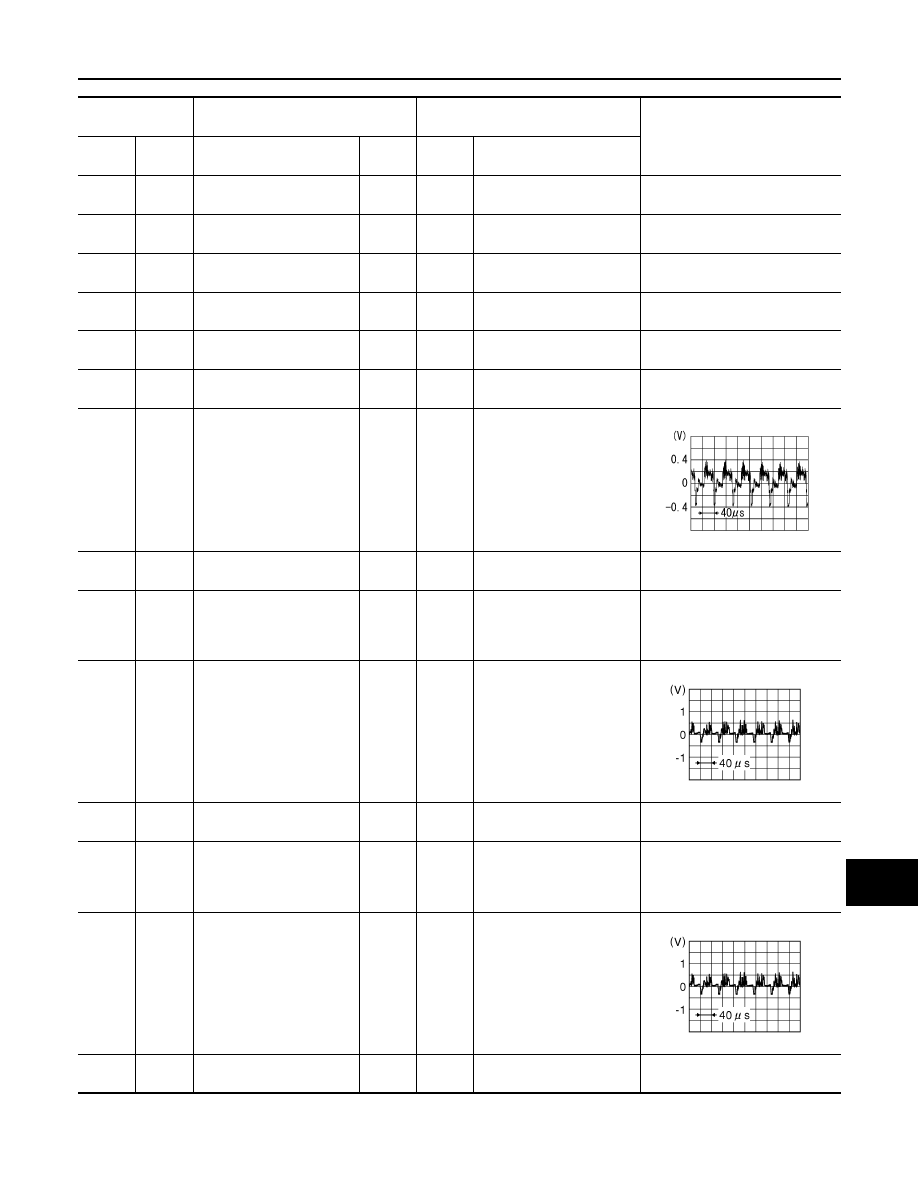
24
(G)
Ground
Camera image signal
Output
ON
When camera image dis-
play
25
(B)
Ground
Rear camera ground
—
ON
—
0 V
26
(R)
Ground
Rear camera power supply
Output
ON
CAMERA selected
or
Shift selector in R (reverse)
position.
6.0 V
28
(W)
27
(Shield)
Rear camera image signal
Input
ON
CAMERA selected
or
Shift selector in R (reverse)
position.
29
(Y)
Ground
Side camera LH ground
—
ON
—
0 V
30
(L)
Ground
Side camera LH power
supply
Output
ON
CAMERA selected
or
Shift selector in R (reverse)
position.
6.0 V
32
(G)
31
(Shield)
Side camera LH image sig-
nal
Input
ON
CAMERA selected
or
Shift selector in R (reverse)
position.
33
(L)
Ground
Side camera RH ground
—
ON
—
0 V
SKIB2251J
JSNIA0834GB
JSNIA0834GB