Nissan Qashqai J11. Manual - part 2113


  Index      Nissan     Nissan Qashqai J11 - Service and Repair Manual


Search            


Content   ..  2111  2112  2113  2114   ..


Nissan Qashqai J11. Manual - part 2113


AV

SYSTEM

AV-141

< SYSTEM DESCRIPTION >

[NAVIGATION]

C

D

E

F

G

H

I

J

K

L

M

B

A

O

P

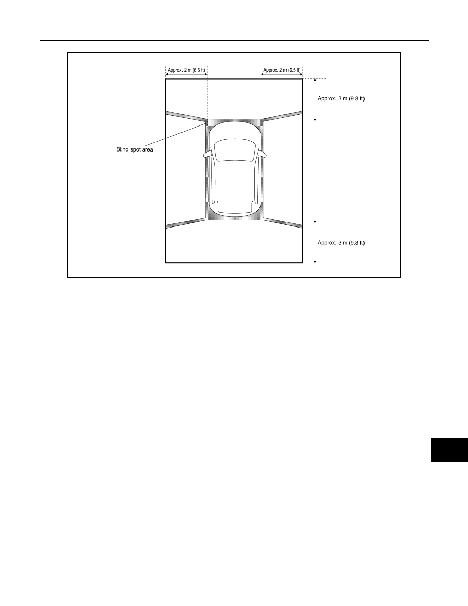
Birds-Eye view display area

AWNIA3142GB

AV-142

< SYSTEM DESCRIPTION >

[NAVIGATION]

DIAGNOSIS SYSTEM (AV CONTROL UNIT)

DIAGNOSIS SYSTEM (AV CONTROL UNIT)

Description

INFOID:0000000010435655

The AV control unit on board diagnosis performs the functions listed in the table below:

Perform CONSULT diagnosis if the AV control unit on board diagnosis does not start or the screen does not
display anything.

On Board Diagnosis Function

INFOID:0000000010435656

METHOD OF STARTING

1.

Turn the ignition ON.

Mode

Item

Content

Version

Version data of the AV control unit is dis-
played.

User Configuration

Touch Display Calibration

Allows correction of the position detec-
tion accuracy of the touch panel.

Radio

FM monitor

Monitors the dynamic values of the cur-
rent tuner

AM monitor

SXM monitor

Version data is displayed.

System State

Running System Status

• SD card slot Access
• Power Supply 
• Speed Signal
• Direction Signal
• Illumination Signal
• GPS Antenna 
• GPS Tracking 
• Satellites Visible 
• Satellites Tracked 
• Microphone Current 
• Steering wheel key
• Radio Antenna 
• SXM Antenna 
• USB Device 

• iPod

®

 firmware version 

• BT  Status 

The current system status is displayed.

Speaker Test 4kHz

This activates a sequence of test tone 
outputs to the audio circuits one after the 
other for 1 second. 

Speaker Test 100Hz

Display-Test

This provides a test sequence where 
test displays (plain colored display: e.g. 
white, black, red, blue, green) are shown 
one after the other. 
The respective color is shown for an in-
dicated period of time (parameter). After 
the display test, the design of the display 
previously available is stored. While the 
screen shows a plain colored display, a 
pixel malfunction may be detected.

Self Test

• SD Card Access 
• BT Module Access
• Radio Antenna
• GPS Antenna
• SXM Antenna

A system self test is executed and the 
results are stored into the error memory.

AV

DIAGNOSIS SYSTEM (AV CONTROL UNIT)

AV-143

< SYSTEM DESCRIPTION >

[NAVIGATION]

C

D

E

F

G

H

I

J

K

L

M

B

A

O

P

2.

While pressing the APPS button, turn the TUNE-SCROLL dial
counterclockwise 3 or more clicks, then clockwise 3 or more
clicks, then counterclockwise 3 or more clicks. Shifting from cur-
rent screen to previous screen is performed by pressing BACK
button.

3.

The trouble diagnosis initial screen is displayed, and Version,
User Config, Radio, System State or Self Test can be selected.

CONSULT Function

INFOID:0000000010435657

CONSULT FUNCTIONS

CONSULT performs the following functions via communication with the AV control unit.

ECU IDENTIFICATION

The part number of AV control unit is displayed.

SELF DIAGNOSTIC RESULT

Refer to 

AV-151, "DTC Index"

.

DATA MONITOR

CONFIGURATION

Refer to 

AV-178, "CONFIGURATION (AV CONTROL UNIT) : Description"

.

CAN DIAG SUPPORT MNTR

Refer to 

LAN-21, "CAN Diagnostic Support Monitor"

.

ALNIA1591ZZ

ALNIA1378ZZ

Direct Diagnostic Mode

Description

Ecu Identification

The AV control unit part number is displayed.

Self Diagnostic Result

The AV control unit self diagnostic results are displayed.

Data Monitor

The AV control unit input/output data is displayed in real time.

Configuration

• The vehicle specification can be read and saved.
• The vehicle specification can be written when replacing AV control unit.

CAN Diag Support Mntr

• The result of transmit/receive diagnosis of AV communication is displayed.
• The result of transmit/receive diagnosis of CAN communication is displayed.

Monitor Item [Unit]

Description

VHCL SPD SIG [On/Off]

Indicates vehicle speed signal received from combination meter on CAN communication 
line.

ILLUM SIG [On/Off]

Indicates condition of illumination signal for the AV control unit.

IGN SIG [On/Off]

Indicates condition of ignition signal.

REV SIG [On/Off]

Indicates condition of reverse signal received from BCM.

AV-144

< SYSTEM DESCRIPTION >

[NAVIGATION]

DIAGNOSIS SYSTEM (AROUND VIEW MONITOR CONTROL UNIT)

DIAGNOSIS SYSTEM (AROUND VIEW MONITOR CONTROL UNIT)

WITHOUT DRIVER ASSISTANCE SYSTEM

WITHOUT DRIVER ASSISTANCE SYSTEM : CONSULT Function

INFOID:0000000010435658

CONSULT FUNCTIONS

CONSULT performs the following functions via communication with the around view monitor control unit.

ECU IDENTIFICATION

The part number of around view monitor control unit is displayed.

SELF DIAGNOSTIC RESULT

Refer to 

AV-154, "WITHOUT DRIVER ASSISTANCE SYSTEM : DTC Index"

.

DATA MONITOR

WORK SUPPORT

Direct Diagnostic Mode

Description

Ecu Identification

The around view monitor control unit part number is displayed.

Self Diagnostic Result

The around view monitor control unit self diagnostic results are displayed.

Data Monitor

The around view monitor control unit input/output data is displayed in real time.

Work support

The settings for around view monitor control unit functions can be changed.

Configuration

• The vehicle specification can be read and saved.
• The vehicle specification can be written when replacing around view monitor control unit.

CAN Diag Support Mntr

The result of transmit/receive diagnosis of CAN communication is displayed.

Monitor Item

Description

ST ANGLE SENSOR SIGNAL [On/Off]

Indicates condition of steering angle sensor signal.

REVERSE SIGNAL [On/Off]

Indicates selector lever position.

VEHICLE SPEED SIGNAL [mph/km/h]

Indicates condition of vehicle speed signal.

CAMERA SWITCH SIGNAL [On/Off]

Indicates condition of camera switch signal.

CAMERA OFF SIGNAL [On/Off]

Indicates condition of camera OFF signal.

ST ANGLE SENSOR TYPE [Absolute]

Indicates steering angle sensor type.

ST GEAR RATIO TYPE [Type O]

Indicates steering gear ratio type.

STEERING POSITION [LHD/RHD]

Indicates LH or RH drive type.

SHIFT LEVER POSITION

Indicates Shift Lever Position.

WHEEL SPEED

• Recieve the Wheel Speed signal 

 ON.

• Not recieve the Wheel Speed signal 

 OFF

REAR CAMERA IMAGE SIGNAL [OK/
NG]

Indicates condition of camera image signal. 

F-CAMERA IMAGE SIGNAL [OK/NG]

Indicates condition of camera image signal. 

DR-SIDE CAMERA IMAGE SIG [OK/
NG]

Indicates condition of camera image signal. 

PA-SIDE CAMERA IMAGE SIG [OK/
NG]

Indicates condition of camera image signal. 

Support Item

Setting

Description

NON-VIEWABLE AREA REMINDER

ON

ON/OFF setting of non-viewable area can be performed.

OFF

PREDICTIVE COURSE LINE
DISPLAY

ON

ON/OFF setting of predictive course line display can be performed.

OFF


Content   ..  2111  2112  2113  2114   ..