Content .. 2080 2081 2082 2083 ..
Nissan Qashqai J11. Manual - part 2082
AV
DIAGNOSIS SYSTEM (AUDIO UNIT)
AV-17
< SYSTEM DESCRIPTION >
[AUDIO SYSTEM]
C
D
E
F
G
H
I
J
K
L
M
B
A
O
P
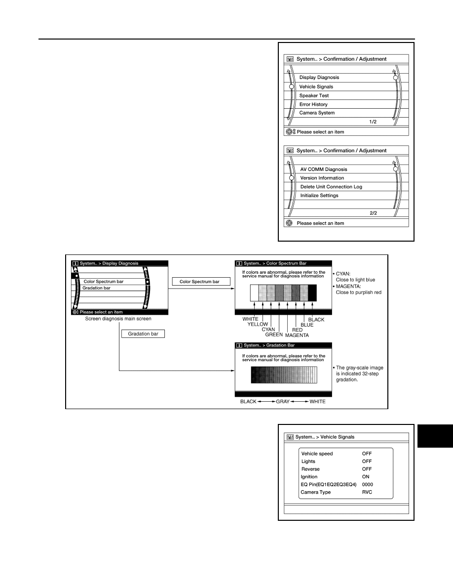
2.
Select each switch on the Confirmation/Adjustment screen to
display the relevant trouble diagnosis screen. Press the BACK
switch to return to the initial Confirmation/Adjustment screen.
Display Diagnosis
Vehicle Signals
A comparison check can be made of each actual vehicle signal and
the signals recognized by the system.
Speaker Test
AWNIA3343ZZ
AWNIA2632GB
AWNIA3344ZZ