Content .. 1975 1976 1977 1978 ..
Nissan Qashqai J11. Manual - part 1977
CHG
SERVICE DATA AND SPECIFICATIONS (SDS)
CHG-55
< SERVICE DATA AND SPECIFICATIONS (SDS)
[TYPE 2]
C
D
E
F
G
H
I
J
K
L
B
A
O
P
N
SERVICE DATA AND SPECIFICATIONS (SDS)
SERVICE DATA AND SPECIFICATIONS (SDS)
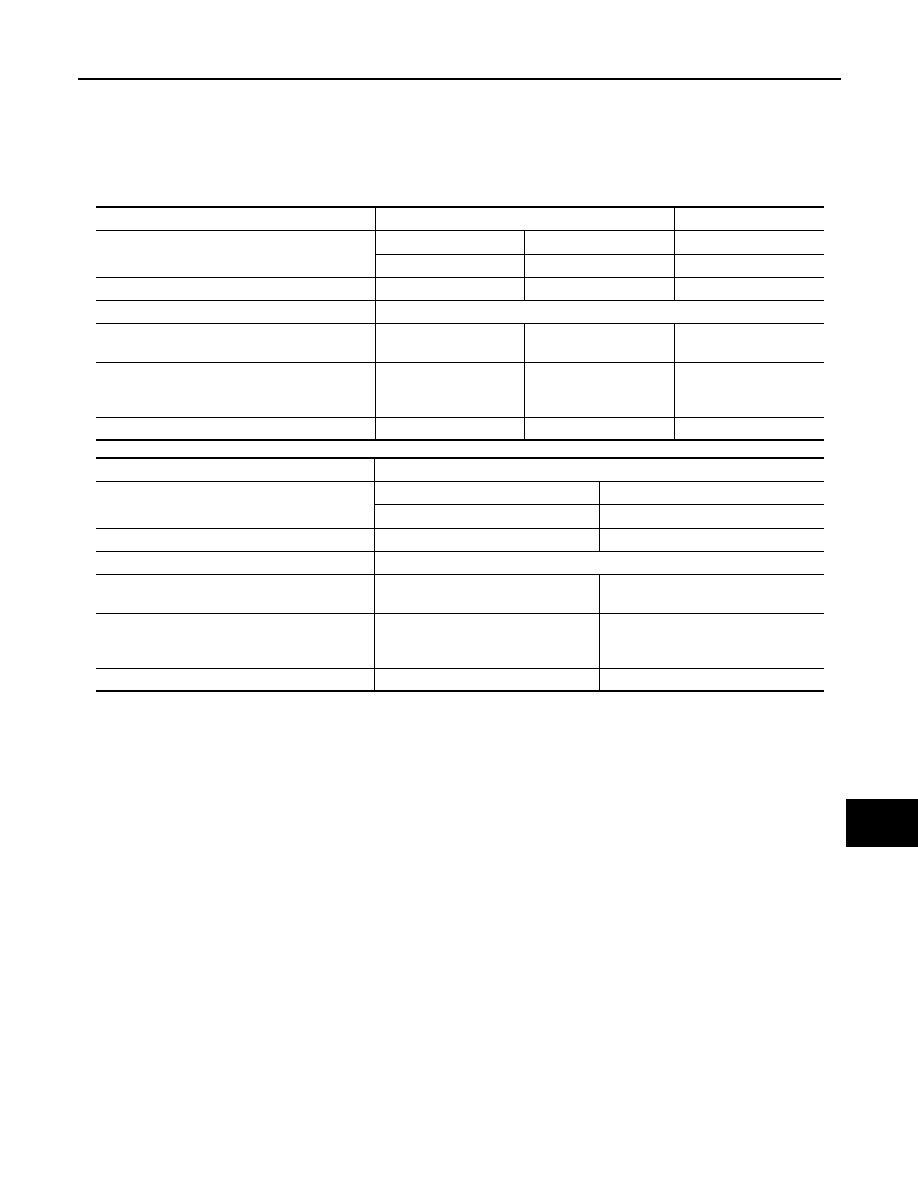
Alternator
INFOID:0000000010713263
Applied model
HR
R9M
Type
F 000 BL0 814
TG12C164
F 000 BL0 814
BOSCH make
Valeo make
BOSCH make
Nominal rating
[V - A]
14 - 150
12 - 120
14 - 150
Ground polarity
Negative
Minimum revolution under no-load
(When 13.5 V is applied)
[rpm]
Less than 1,500
Less than 1,300
Less than 1,500
Hot output current
(When 13.5 V is applied)
[A/rpm]
More than 84/1,500
More than 124/2,500
More than 151/5,000
More than 69/1,800
More than 104/3,000
More than 120/6,000
More than 84/1,500
More than 124/2,500
More than 151/5,000
Regulated output voltage
[V]
—
14.1 - 14.5
—
Applied model
MR
Type
TG12C163
F 000 BL0 890
Valeo make
BOSCH make
Nominal rating
[V - A]
12 - 120
14 - 150
Ground polarity
Negative
Minimum revolution under no-load
(When 13.5 V is applied)
[rpm]
Less than 1,300
Less than 1,500
Hot output current
(When 13.5 V is applied)
[A/rpm]
More than 69/1,800
More than 104/3,000
More than 120/6,000
More than 84/1,500
More than 124/2,500
More than 151/5,000
Regulated output voltage
[V]
14.1 - 14.5
—