Nissan Qashqai J11. Manual - part 1965


  Index      Nissan     Nissan Qashqai J11 - Service and Repair Manual


Search            


Content   ..  1963  1964  1965  1966   ..


Nissan Qashqai J11. Manual - part 1965


CHG

COMPONENT PARTS

CHG-7

< SYSTEM DESCRIPTION >

[TYPE 1]

C

D

E

F

G

H

I

J

K

L

B

A

O

P

N

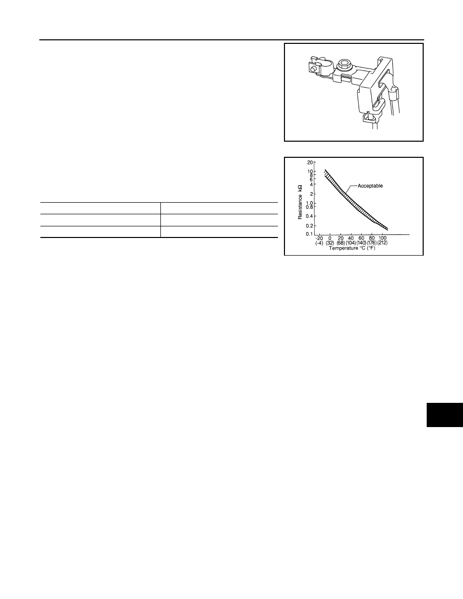
The battery current sensor is installed to the battery negative cable.
The sensor measures the charging/discharging current of the bat-
tery.

BATTERY TEMPERATURE SENSOR

Battery temperature sensor is integrated in battery current sensor.
The sensor measures temperature around the battery.
The electrical resistance of the thermistor decreases as temperature
increases.

JPBIA3262ZZ

Temperature [

°

C (

°

F)]

Resistance (k

)

25 (77)

1.9 - 2.1

90 (194)

0.222 - 0.258

SEF012P

CHG-8

< SYSTEM DESCRIPTION >

[TYPE 1]

SYSTEM

SYSTEM

ENERGY MANAGEMENT SYSTEM

ENERGY MANAGEMENT SYSTEM : System Description

INFOID:0000000010431015

SYSTEM DIAGRAM

SYSTEM DESCRIPTION

• Battery current sensor (With battery temperature sensor) measures the charging/discharging current of the

battery and the temperature around the battery.

• IPDM E/R judges battery condition according to the charging/discharging current of the battery and the tem-

perature around the battery.

• IPDM E/R calculates the target power generation voltage according to the battery condition and sends the

calculated value as alternator voltage request signal to ECM via CAN communication.

• ECM transmits alternator voltage request signal to alternator via LIN communication.
• Control module inside alternator controls the power generation voltage based on the received alternator volt-

age request signal.

• Alternator includes a self-diagnosis function and transmits the diagnosis result to ECM via LIN communica-

tion when detecting any malfunction.

• Charge warning lamp turns ON when any of the following symptom occurs while ignition switch is ON:
- Excessive voltage is produced.
- No voltage is produced.
- High voltage is detected from battery positive terminal.
- The communication between alternator and ECM is not available.

NOTE:
Charge warning lamp turns OFF while stop/start system is activated.

JMMIA1760GB

CHG

ECM, IPDM E/R

CHG-9

< ECU DIAGNOSIS INFORMATION >

[TYPE 1]

C

D

E

F

G

H

I

J

K

L

B

A

O

P

N

ECU DIAGNOSIS INFORMATION

ECM, IPDM E/R

List of ECU Reference

INFOID:0000000010463846

ECU

Reference

ECM (HR engine)

ECH-59, "Fail-safe"

ECH-59, "Reference Value"

ECH-71, "DTC Index"

ECM (K9K engine)

ECK-76, "Reference Value"

ECK-88, "Fail-safe"

ECK-95, "DTC Inspection Priority Chart"

ECK-97, "DTC Index"

ECM (R9M engine)

EC9-89, "Reference Value"

EC9-101, "Fail-safe"

EC9-107, "DTC Inspection Priority Chart"

EC9-108, "DTC Index"

IPDM E/R

PCS-21, "Reference Value"

PCS-33, "Fail-safe"

PCS-36, "DTC Inspection Priority Chart"

PCS-37, "DTC Index"

CHG-10

< WIRING DIAGRAM >

[TYPE 1]

CHARGING SYSTEM

WIRING DIAGRAM

CHARGING SYSTEM

Wiring Diagram

INFOID:0000000010431017

JRMWE9284GB


Content   ..  1963  1964  1965  1966   ..