Content .. 1930 1931 1932 1933 ..
Nissan Qashqai J11. Manual - part 1932
LAN
MALFUNCTION AREA CHART
LAN-321
< DTC/CIRCUIT DIAGNOSIS >
[CAN SYSTEM (TYPE 551)]
C
D
E
F
G
H
I
J
K
L
B
A
O
P
N
DTC/CIRCUIT DIAGNOSIS
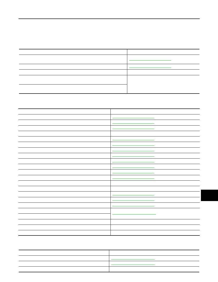
MALFUNCTION AREA CHART
Main Line
INFOID:0000000011853734
Branch Line
INFOID:0000000011853735
Short Circuit
INFOID:0000000011853736
Malfunction area
Reference
Main line between ABS actuator and electric unit (control unit) and data link con-
nector
Main line between data link connector and chassis control module connector
Main line between chassis control module and 4WD control unit
—
Main line between A/C auto amp. and front camera unit connector (With auto-
matic air conditioner)
—
Main line between A/C amp. and front camera unit connector (Except automatic
air conditioner)
Malfunction area
Reference
ECM branch line circuit
ABS actuator and electric unit (control unit) branch line circuit
IPDM E/R branch line circuit
TCM branch line circuit
—
Data link connector branch line circuit
Electric park brake control unit branch line
EPS control unit branch line circuit
Steering lock unit branch line circuit
Combination meter branch line circuit
Steering angle sensor branch line circuit
Air bag diagnosis sensor unit branch line circuit
Chassis control module branch line circuit
Sonar control unit branch line circuit
—
4WD control unit branch line circuit
—
BCM branch line circuit
NAVI control unit branch line circuit
Around view monitor control unit branch line circuit
A/C auto amp. branch line circuit (With automatic air conditioner)
LAN-100, "Diagnosis Procedure"
A/C amp. branch line circuit (Except automatic air conditioner)
Front camera unit branch line circuit
—
Distance sensor branch line circuit (CAN communication circuit 2)
—
Distance sensor branch line circuit (Chassis communication circuit)
—
Malfunction area
Reference
CAN communication circuit 1
LAN-105, "Diagnosis Procedure"
CAN communication circuit 2
LAN-107, "Diagnosis Procedure"
Chassis communication circuit
—