Nissan Qashqai J11. Manual - part 1880


  Index      Nissan     Nissan Qashqai J11 - Service and Repair Manual


Search            


Content   ..  1878  1879  1880  1881   ..


Nissan Qashqai J11. Manual - part 1880


LAN

SYSTEM

LAN-113

< SYSTEM DESCRIPTION >

[CAN GATEWAY]

C

D

E

F

G

H

I

J

K

L

B

A

O

P

N

SYSTEM DESCRIPTION

SYSTEM

System Description

INFOID:0000000010377240
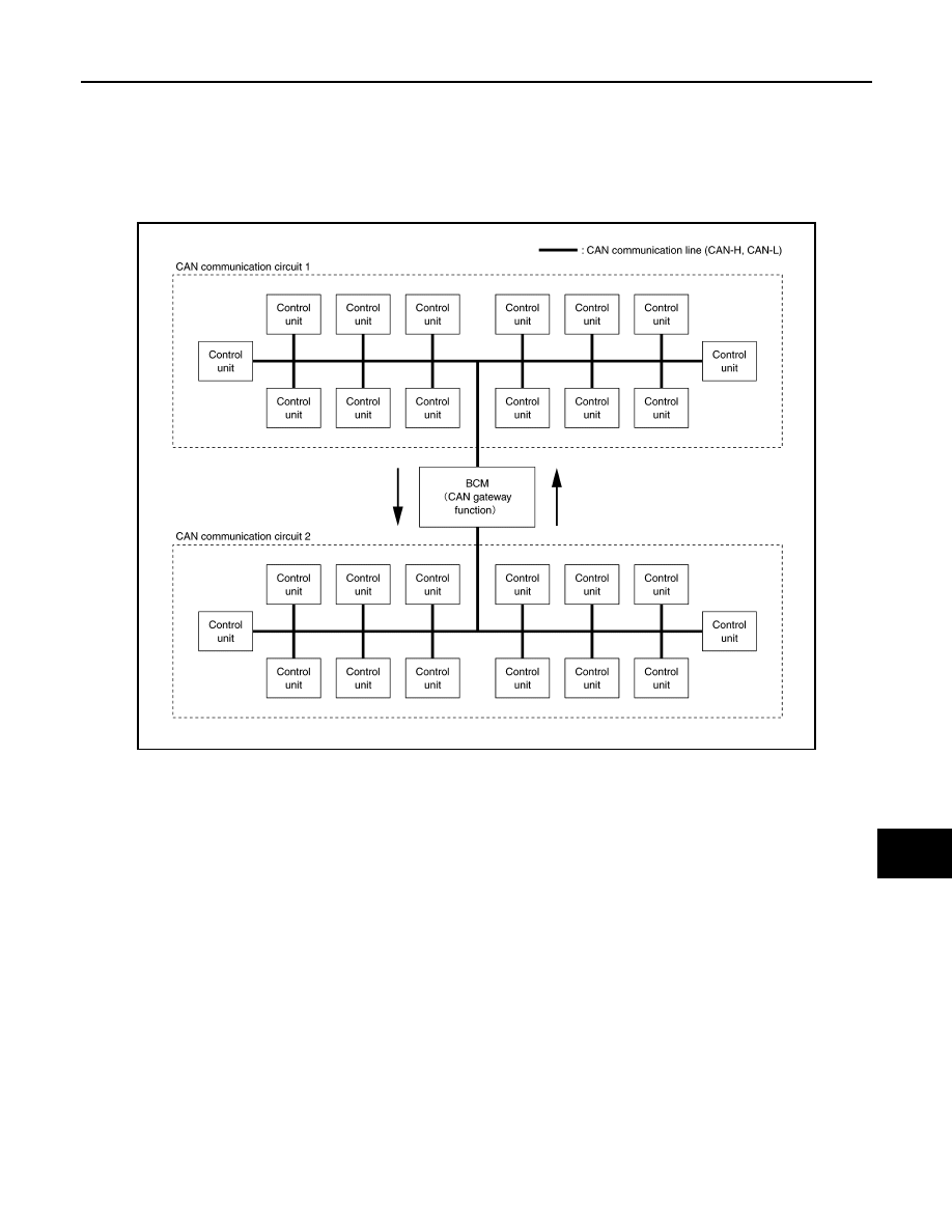
SYSTEM DIAGRAM

SYSTEM DESCRIPTION

• The BCM has a CAN gateway function.
• The BCM communicates between two CAN communication circuits.
• The BCM selects and transmits only necessary information.

JSMIA1666GB

LAN-114

< SYSTEM DESCRIPTION >

[CAN GATEWAY]

DIAGNOSIS SYSTEM (CAN GATEWAY)

DIAGNOSIS SYSTEM (CAN GATEWAY)

CONSULT Function

INFOID:0000000010377241

APPLICATION ITEM

CONSULT performs the following functions via CAN communication with CAN gateway.

ECU IDENTIFICATION

The CAN gateway part number is displayed.

SELF DIAGNOSTIC RESULT

Refer to 

LAN-115, "DTC Index"

.

• When “CRNT” is displayed on self-diagnosis result
- The system is presently malfunctioning.
• When “PAST” is displayed on self-diagnosis result
- System malfunction in the past is detected, but the system is presently normal.

Freeze Frame Data (FFD)

When DTC is detected, a vehicle state shown below is recorded and displayed on CONSULT.

DATA MONITOR

CONFIGURATION

CAUTION:

Follow the instructions listed below. Failure to do this may cause malfunctions to the BCM.:
• When replacing BCM you must perform “Read / Write Configuration” or “Manual Configuration” with

CONSULT.

• Complete the procedure of “Read / Write Configuration” or “Manual Configuration” in order.
• If you set incorrect “Read / Write Configuration” or “Manual Configuration”, incidents might occur.
• Configuration is different for each vehicle model. Confirm configuration of each vehicle model.
• Never perform “Read / Write Configuration” or “Manual Configuration” except for new BCM. 

Diagnosis mode

Function Description

Ecu Identification

The CAN gateway software number is displayed.

Self Diagnostic Result

Displays the diagnosis results of BCM CAN gateway function.

Data Monitor

Displays real-time input/output data of BCM CAN gateway function.

Configuration

• Read and save the vehicle specification.
• Write the vehicle specification when replacing of BCM.

Item name

Display item

Milage
(Kirometers)

Displays the total mileage when a DTC is detected.

Monitor item

Description

CAN GW MODE
(UNCONF/MALF/NORMAL)

Displays the status of BCM CAN gateway function.

IGN SIGNAL
(Off/On)

Displays the status of ignition switch.

Function

Description

Read / Write Configuration

Before Replace ECU

• Reads the vehicle configuration of current BCM.
• Saves the read vehicle configuration.

After Replace ECU

Writes the vehicle configuration with saved data.

Manual Configuration

Writes the vehicle configuration with manual selection.

LAN

CAN GATEWAY

LAN-115

< ECU DIAGNOSIS INFORMATION >

[CAN GATEWAY]

C

D

E

F

G

H

I

J

K

L

B

A

O

P

N

ECU DIAGNOSIS INFORMATION

CAN GATEWAY

Reference Value

INFOID:0000000010377242

VALUES ON THE DIAGNOSIS TOOL

NOTE:
The following table includes information (items) inapplicable to this vehicle. For information (items) applicable
to this vehicle, refer to CONSULT display items.

DTC Index

INFOID:0000000010377243

Monitor item

Condition

Value/Status

CAN GW MODE

When the configuration of the BCM CAN gateway function is not writ-
ten

UNCONF

When the BCM CAN Gateway function is malfunction

MALF

When BCM CAN Gateway function is normal.

NORMAL

IGN SIGNAL

Ignition switch in OFF or ACC position

Off

Ignition switch in ON position

On

DTC

Reference

No DTC is detected.
Further testing may be required.

B2600-46: CONFIG ERROR

LAN-117, "DTC Description"

B2600-55: CONFIG ERROR

LAN-118, "DTC Description"

LAN-116

< BASIC INSPECTION >

[CAN GATEWAY]

CONFIGURATION (CAN GATEWAY)

BASIC INSPECTION

CONFIGURATION (CAN GATEWAY)

Work Procedure

INFOID:0000000010377244

1.

WRITING MODE SELECTION

CONSULT Configuration

Select “Re/programming, Configuration” of CAN gateway.

When writing saved data>>GO TO 2.
When writing manually>>GO TO 3.

2.

PERFORM “AFTER REPLACE ECU” OF “READ / WRITE CONFIGURATION”

CONSULT Configuration

Perform “After Replace ECU” of “Read / Write Configuration”.

>> GO TO 4.

3.

PERFORM “MANUAL CONFIGURATION”

CONSULT Configuration

1.

Select “Manual Configuration”.

2.

Touch “Next”.

3.

Touch “OK”.

4.

Check that the configuration has been successfully written and touch “End”.

>> GO TO 4.

4.

CHECK ALL ECU SELF-DIAGNOSIS RESULTS

1.

Erase all ECU self-diagnosis results using CONSULT.

2.

Turn the ignition switch OFF.

3.

Turn the ignition switch ON and wait for 2 seconds or more.

4.

Check that all ECU self-diagnosis results have no DTC (e.g. U1000 and U1001) of CAN communication.

>> WORK END


Content   ..  1878  1879  1880  1881   ..