Content .. 1877 1878 1879 1880 ..
Nissan Qashqai J11. Manual - part 1879
LAN
CHASSIS COMMUNICATION CIRCUIT
LAN-109
< DTC/CIRCUIT DIAGNOSIS >
[CAN]
C
D
E
F
G
H
I
J
K
L
B
A
O
P
N
CHASSIS COMMUNICATION CIRCUIT
Diagnosis Procedure
INFOID:0000000010339753
1.
CHECK CAN DIAGNOSIS
Check the CAN diagnosis results from CONSULT to see that the CAN communication circuit 1 and CAN com-
munication circuit 2 have no malfunction.
Are the CAN communication 1 and CAN communication 2 circuits normal?
YES
>> GO TO 2.
NO
>> Check and repair CAN communication circuit 1 and/or CAN communication circuit 2.
2.
CONNECTOR INSPECTION
1.
Turn the ignition switch OFF.
2.
Disconnect the battery cable from the negative terminal.
3.
Check the terminals and connectors of the chassis control module for damage, bend and loose connec-
tion (unit side and connector side).
Is the inspection result normal?
YES
>> GO TO 3.
NO
>> Repair the terminal and connector.
3.
CHECK HARNESS CONTINUITY (OPEN CIRCUIT)
1.
Disconnect the connector of chassis control module.
2.
Check the continuity between the chassis control module harness connector terminals.
Is the inspection result normal?
YES
>> GO TO 4.
NO
>> Check the harness and repair or replace the root cause.
4.
CHECK HARNESS CONTINUITY (SHORT CIRCUIT)
1.
Disconnect all the unit connectors on chassis communication circuit.
2.
Check the continuity between the chassis control module harness connector terminals.
Is the inspection result normal?
YES
>> GO TO 5.
NO
>> Check the harness and repair or replace the root cause.
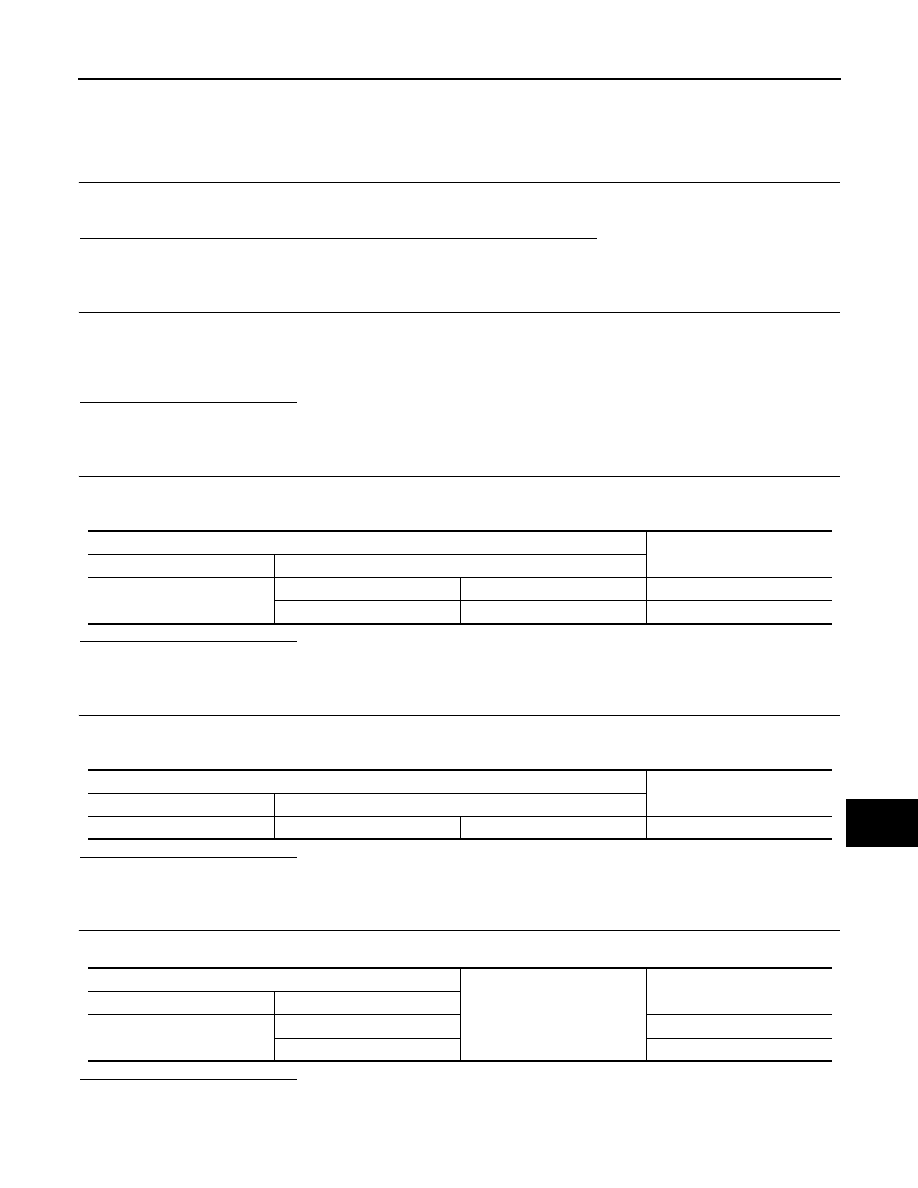
5.
CHECK HARNESS CONTINUITY (SHORT CIRCUIT)
Check the continuity between the chassis control module harness connector and the ground.
Is the inspection result normal?
YES
>> GO TO 6.
NO
>> Check the harness and repair or replace the root cause.
Chassis control module harness connector
Continuity
Connector No.
Terminal No.
M43
11
19
Existed
8
7
Existed
Chassis control module harness connector
Continuity
Connector No.
Terminal No.
M43
11
8
Not existed
Chassis control module harness connector
Ground
Continuity
Connector No.
Terminal No.
M43
11
Not existed
8
Not existed