Content .. 1820 1821 1822 1823 ..
Nissan Qashqai J11. Manual - part 1822
BCS-14
< SYSTEM DESCRIPTION >
SYSTEM
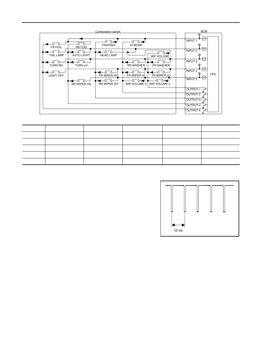
Combination switch circuit
Combination switch INPUT-OUTPUT system list
COMBINATION SWITCH READING FUNCTION
Description
• BCM reads the status of the combination switch at 10 ms interval
normally.
NOTE:
BCM reads the status of the combination switch at 60 ms interval
when BCM is controlled at low power consumption control mode.
• BCM operates as follows and judges the status of the combination switch.
- It operates the transistor on OUTPUT side in the following order: OUTPUT 5
→
4
→
3
→
2
→
1, and outputs
voltage waveform.
- The voltage waveform of OUTPUT corresponding to the formed circuit is input into the interface on INPUT
side if any (1 or more) switches are ON.
System
OUTPUT 1
OUTPUT 2
OUTPUT 3
OUTPUT 4
OUTPUT 5
INPUT 1
—
HI BEAM
PASSING
RR FOG
FR FOG
INPUT 2
WIP VOLUME 1
—
HEADLAMP
AUTO LIGHT
TAIL LAMP
INPUT 3
FR WASHER
RR WASHER
—
TURN LH
TURN RH
INPUT 4
FR WIPER LO
FR WIPER HI
FR WIPER INT/AUTO
—
LIGHT OFF
INPUT 5
WIP VOLUME 2
WIP VOLUME 3
RR WIPER INT
RR WIPER ON
—
JMMIA1754GB
JMMIA1637GB