Nissan Qashqai J11. Manual - part 174
CO-100
< REMOVAL AND INSTALLATION >
[R9M]
WATER PUMP
WATER PUMP
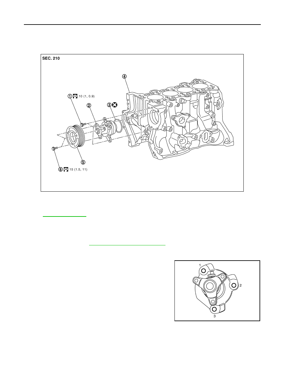
Exploded View
INFOID:0000000010416542
for symbols in the figure.
Removal and Installation
INFOID:0000000010416543
REMOVAL
1.
Remove engine. Refer to
EM-431, "Removal and Installation"
.
2.
Remove water pump pulley.
3.
Remove water pump.
• Loosen mounting bolts in reverse order as shown in the figure.
CAUTION:
• Handle water pump vane so that it does not contact any
other parts.
• Water pump cannot be disassembled and should be
replaced as a unit.
INSTALLATION
Note the following, and install in the reverse order of removal.
Water pump
1.
Water pump bolt
2.
Water pump
3.
O-ring
4.
Cylinder block
E1BIA0585GB
JPBIA0746ZZ