Nissan Qashqai J11. Manual - part 155


  Index      Nissan     Nissan Qashqai J11 - Service and Repair Manual


Search            


Content   ..  153  154  155  156   ..


Nissan Qashqai J11. Manual - part 155


WATER PUMP

CO-23

< REMOVAL AND INSTALLATION >

[HRA2DDT]

C

D

E

F

G

H

I

J

K

L

M

A

CO

N

P

O

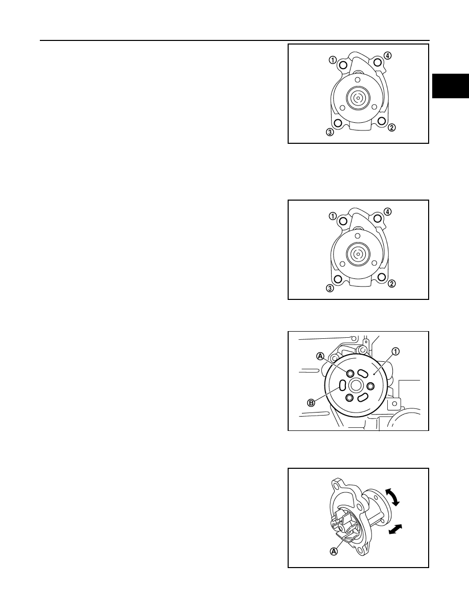
• Loosen mounting bolts in reverse order as shown in the figure.
• Engine coolant will leak from cylinder block, so have a recep-

tacle ready below.

CAUTION:

• Handle water pump vane so that it does not contact any

other parts.

• Water pump cannot be disassembled and should be

replaced as a unit.

INSTALLATION

Note the following, and install in the reverse order of removal.

Water pump

• Tighten mounting bolts in numerical order as shown in the figure. 

CAUTION:

Do not re-use gasket.

Water pump pulley

CAUTION:

Never install mounting bolts (A) to oblong holes (B) of water
pump pulley (1). 

Inspection

INFOID:0000000010416356

INSPECTION AFTER REMOVAL

• Check visually that there is no significant dirt or rusting on water

pump body and vane (A).

• Check that there is no looseness in vane shaft, and that it turns

smoothly when rotated by hand.

• Replace water pump, if necessary.

INSPECTION AFTER INSTALLATION

KBIA3393J

KBIA3393J

PBIC3809E

PBIC3808E

CO-24

< REMOVAL AND INSTALLATION >

[HRA2DDT]

WATER PUMP

• Check for leakage of engine coolant using the radiator cap tester adapter (commercial service tool) and the

radiator cap tester (commercial service tool). Refer to 

CO-19, "Inspection"

.

• Start and warm up the engine. Check visually that there is no leakage of engine coolant.

THERMOSTAT

CO-25

< REMOVAL AND INSTALLATION >

[HRA2DDT]

C

D

E

F

G

H

I

J

K

L

M

A

CO

N

P

O

THERMOSTAT

Exploded View

INFOID:0000000010416357

Refer to 

GI-4, "Components"

 for symbol marks in the figure.

Removal and Installation

INFOID:0000000010416358

NOTE:
When removing components such as hoses, tubes/lines, etc., cap or plug openings to prevent fluid from spill-
ing.

REMOVAL

1.

Drain engine coolant from radiator. Refer to 

CO-11, "Draining"

CAUTION:

Perform this step when engine is cold.

2.

Remove intake manifold. Refer to 

EM-25, "Removal and Installation"

3.

Disconnect water hose from water inlet.

4.

Disconnect water inlet connector.

5.

Remove thermostat and water inlet assembly.
• Engine coolant will leak from cylinder block, so have a receptacle ready below.
• NOTE:

Thermostat can not be separated from water inlet.

INSTALLATION

Note the following, and install in the reverse order of removal.

Thermostat 

• Thermostat can not be separated from water inlet. 

1.

Water inlet

2.

Water inlet gasket

3.

Cylinder block

E1BIA1118GB

CO-26

< REMOVAL AND INSTALLATION >

[HRA2DDT]

THERMOSTAT

Water inlet

CAUTION:

Do not reuse water inlet gasket.

Inspection

INFOID:0000000010416359

INSPECTION AFTER REMOVAL

Thermostat

• Place a thread (A) so that it is caught in the valves of thermostat

(1). Immerse fully in a container (B) filled with water. Heat while
stirring.

• The valve opening temperature is the temperature at which the

valve opens and falls from the thread.

• Continue heating. Check the full open valve lift amount.
• After checking the maximum valve lift amount, lower the water

temperature and check the valve closing temperature. 

• If out of the standard, replace thermostat.

INSPECTION AFTER INSTALLATION

• Check for leakage of engine coolant using the radiator cap tester adapter (commercial service tool) and the

radiator cap tester (commercial service tool). Refer to 

CO-19, "Inspection"

.

• Start and warm up the engine. Check visually that there is no leakage of engine coolant.

Standard: Refer to 

CO-29, "Thermostat"

.

PBIC3314J


Content   ..  153  154  155  156   ..