Nissan Qashqai J11. Manual - part 1517


  Index      Nissan     Nissan Qashqai J11 - Service and Repair Manual


Search            


Content   ..  1515  1516  1517  1518   ..


Nissan Qashqai J11. Manual - part 1517


PWC-48

< DTC/CIRCUIT DIAGNOSIS >

POWER WINDOW MOTOR

Is the inspection result normal?

YES

>> Replace front power window motor (passenger side). Refer to 

GW-26, "Disassembly and Assem-

bly"

.

NO

>> GO TO 2.

2.

CHECK FRONT POWER WINDOW MOTOR (PASSENGER SIDE) CIRCUIT

1.

Turn ignition switch OFF.

2.

Disconnect front power window switch (passenger side) connector.

3.

Check continuity between front power window switch (passenger side) harness connector and front power
window motor (passenger side) harness connector.

4.

Check continuity between front power window switch (passenger side) harness connector and ground.

Is the inspection result normal?

YES

>> Replace front power window switch (passenger side). Refer to 

PWC-68, "FRONT POWER WIN-

DOW SWITCH (PASSENGER SIDE) : Removal and Installation"

.

NO

>> Repair or replace harness.

REAR LH

REAR LH : Component Function Check

INFOID:0000000010325685

1.

CHECK FUNCTION

Check rear power window motor LH operation with power window main switch (rear LH switch) or rear power
window switch LH.
Is the inspection result normal?

YES

>> INSPECTION END

NO

>> Refer to 

PWC-48, "REAR LH : Diagnosis Procedure"

.

REAR LH : Diagnosis Procedure

INFOID:0000000010286504

1.

CHECK REAR POWER WINDOW MOTOR LH INPUT SIGNAL

1.

Turn ignition switch OFF.

2.

Disconnect rear power window motor LH connector.

3.

Turn ignition switch ON.

4.

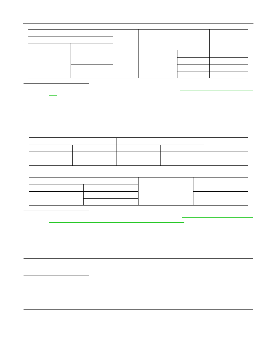
Check voltage between rear power window motor LH harness connector and ground.

(+)

(

)

Condition

Voltage

Front power window motor (passenger side)

Connector

Terminal 

D15

1

Ground

Front power window 
switch
(passenger side)

UP

9 - 16 V

DOWN

0 - 1 V

2

UP

0 - 1 V

DOWN

9 - 16 V

Front power window switch (passenger side)

Front power window motor (passenger side)

Continuity

Connector

Terminal

Connector

Terminal

D7

6

D15

2

Existed

7

1

Front power window switch (passenger side)

Ground

Continuity

Connector

Terminal

D7

6

Not existed

7

POWER WINDOW MOTOR

PWC-49

< DTC/CIRCUIT DIAGNOSIS >

C

D

E

F

G

H

I

J

L

M

A

B

PWC

N

O

P

Is the inspection result normal?

YES

>> Replace rear power window motor LH. Refer to 

GW-30, "Disassembly and Assembly"

.

NO

>> GO TO 2.

2.

CHECK REAR POWER WINDOW MOTOR LH CIRCUIT

1.

Turn ignition switch OFF.

2.

Disconnect rear power window switch LH connector.

3.

Check continuity between rear power window switch LH harness connector and rear power window motor
LH harness connector.

4.

Check continuity between rear power window switch LH connector and ground.

Is the inspection result normal?

YES

>> Replace rear power window switch LH. Refer to 

PWC-69, "Removal and Installation"

.

NO

>> Repair or replace harness.

REAR RH

REAR RH : Component Function Check

INFOID:0000000010325686

1.

 CHECK FUNCTION

Check rear power window motor RH operation with power window main switch (rear RH switch) or rear power
window switch RH.

Is the inspection result normal?

YES

>> INSPECTION END

NO

>> Refer to 

PWC-49, "REAR RH : Diagnosis Procedure"

.

REAR RH : Diagnosis Procedure

INFOID:0000000010286505

1.

CHECK REAR POWER WINDOW MOTOR RH INPUT SIGNAL

1.

Turn ignition switch OFF.

2.

Disconnect rear power window motor RH connector.

3.

Turn ignition switch ON.

4.

Check voltage between rear power window motor RH harness connector and ground.

(+)

(

)

Condition

Voltage

Rear power window motor LH

Connector

Terminal 

D53

1

Ground

Rear power win-
dow switch LH

UP

9 - 16 V

DOWN

0 - 1 V

2

UP

0 - 1 V

DOWN

9 - 16 V

Rear power window switch LH

Rear power window motor LH

Continuity

Connector

Terminal

Connector

Terminal

D54

4

D53

2

Existed

5

1

Rear power window switch LH

Ground

Continuity

Connector

Terminal

D54

4

Not existed

5

PWC-50

< DTC/CIRCUIT DIAGNOSIS >

POWER WINDOW MOTOR

Is the inspection result normal?

YES

>> Replace rear power window motor RH. Refer to 

GW-30, "Disassembly and Assembly"

.

NO

>> GO TO 2.

2.

CHECK REAR POWER WINDOW MOTOR RH CIRCUIT

1.

Turn ignition switch OFF.

2.

Disconnect rear power window switch RH connector.

3.

Check continuity between rear power window switch RH harness connector and rear power window motor
RH harness connector.

4.

Check continuity between rear power window switch RH harness connector and ground.

Is the inspection result normal?

YES

>> Replace rear power window switch RH. Refer to 

PWC-69, "Removal and Installation"

.

NO

>> Repair or replace harness.

(+)

(

)

Condition

Voltage

Rear power window motor RH

Connector

Terminal 

D66

1

Ground

Rear power window 
switch RH 

UP

9 - 16 V

DOWN

0 - 1 V

2

OP

0 - 1 V

DOWN

9 - 16 V

Rear power window switch RH

Rear power window motor RH

Continuity

Connector

Terminal

Connector

Terminal

D67

4

D66

2

Existed

5

1

Rear power window switch RH

Ground

Continuity

Connector

Terminal

D67

4

Not existed

5

ENCODER CIRCUIT

PWC-51

< DTC/CIRCUIT DIAGNOSIS >

C

D

E

F

G

H

I

J

L

M

A

B

PWC

N

O

P

ENCODER CIRCUIT

Component Function Check

INFOID:0000000010325687

1.

CHECK FUNCTION

Check that front door glass (driver side) perform AUTO UP/DOWN operation normally when power window
main switch is operated.

Is the inspection result normal?

YES

>> INSPECTION END

NO

>> Refer to 

PWC-51, "Diagnosis Procedure"

.

Diagnosis Procedure

INFOID:0000000010286506

LHD MODELS

1.

CHECK ENCODER SIGNAL

1.

Turn ignition switch ON.

2.

Check signal between power window main switch harness connector and ground with oscilloscope.

Is the inspection result normal?

YES

>> Replace power window main switch. Refer to 

PWC-68, "POWER WINDOW MAIN SWITCH :

Removal and Installation"

NO

>> GO TO 2.

2.

CHECK ENCODER SIGNAL CIRCUIT

1.

Turn ignition switch OFF.

2.

Disconnect power window main switch connector and front power window motor (driver side) connector.

3.

Check continuity between power window main switch harness connector and front power window motor
(driver side) harness connector.

4.

Check continuity between power window main switch harness connector and ground.

(+)

(

)

Signal

(Reference value)

 Power window main switch 

Connector

Terminal 

D10

4

Ground

Refer to following signal

5

JMKIA5210GB

Power window main switch

Front power window motor (driver side)

Continuity

Connector

Terminal

Connector

Terminal

D10

4

D12

6

Existed

5

1


Content   ..  1515  1516  1517  1518   ..