Nissan Qashqai J11. Manual - part 139


  Index      Nissan     Nissan Qashqai J11 - Service and Repair Manual


Search            


Content   ..  137  138  139  140   ..


Nissan Qashqai J11. Manual - part 139


LU-16

< PRECAUTION >

[MR20DD]

PRECAUTIONS

PRECAUTION

PRECAUTIONS

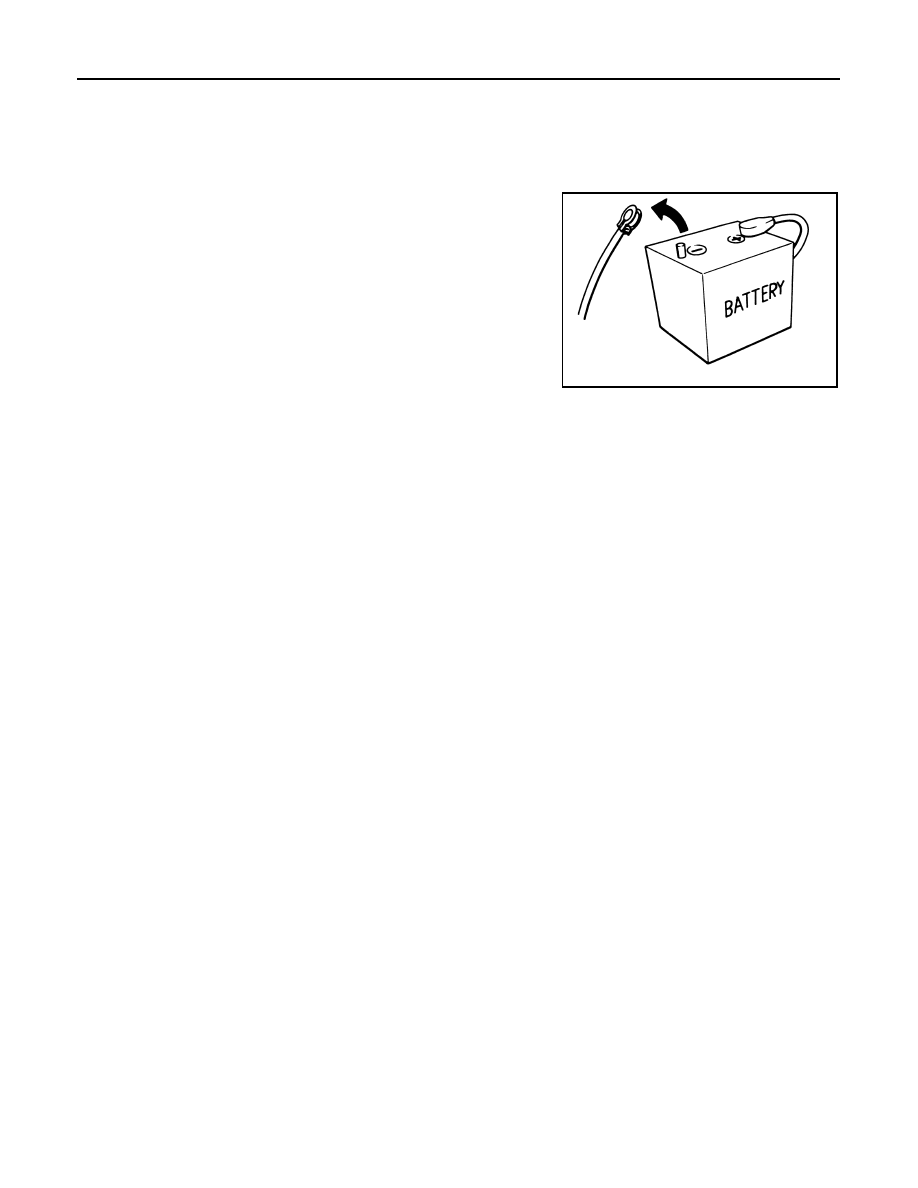
Precautions for Removing Battery Terminal

INFOID:0000000010624147

•  When removing the 12V battery terminal, turn OFF the ignition

switch and wait at least 30 seconds.
NOTE:
ECU may be active for several tens of seconds after the ignition
switch is turned OFF. If the battery terminal is removed before ECU
stops, then a DTC detection error or ECU data corruption may
occur.

•  For vehicles with the 2-batteries, be sure to connect the main bat-

tery and the sub battery before turning ON the ignition switch.
NOTE:
If the ignition switch is turned ON with any one of the terminals of
main battery and sub battery disconnected, then DTC may be
detected.

•  After installing the 12V battery, always check "Self Diagnosis Result" of all ECUs and erase DTC.

NOTE:
The removal of 12V battery may cause a DTC detection error.

Precautions For Engine Service

INFOID:0000000010624148

DISCONNECTING FUEL PIPING

• Before starting work, check no fire or spark producing items are in the work area. 
• Release fuel pressure before disconnecting and disassembly.
• After disconnecting pipes, plug openings to stop fuel leakage.

DRAINING ENGINE COOLANT

Drain engine coolant and engine oil when the engine is cooled.

INSPECTION, REPAIR AND REPLACEMENT

Before repairing or replacing, thoroughly inspect parts. Inspect new replacement parts in the same way, and
replace if necessary.

REMOVAL AND DISASSEMBLY

• When instructed to use SST, use specified tools. Always be careful to work safely, avoid forceful or unin-

structed operations. 

• Exercise maximum care to avoid damage to mating or sliding surfaces.
• Dowel pins are used for several parts alignment. When replacing and reassembling parts with dowel pins,

check that dowel pins are installed in the original position.

• Must cover openings of engine system with a tape or equivalent, to seal out foreign materials.
• Mark and arrange disassembly parts in an organized way for easy troubleshooting and reassembly.
• When loosening nuts and bolts, as a basic rule, start with the one furthest outside, then the one diagonally

opposite, and so on. If the order of loosening is specified, do exactly as specified. Power tools may be used
in the step.

ASSEMBLY AND INSTALLATION

• Use torque wrench to tighten bolts or nuts to specification.
• When tightening nuts and bolts, as a basic rule, equally tighten in several different steps starting with the

ones in center, then ones on inside and outside diagonally in this order. If the order of tightening is specified,
do exactly as specified.

• Replace with new gasket, packing, oil seal or O-ring.
• Thoroughly wash, clean, and air-blow each part. Carefully check engine oil or engine coolant passages for

any restriction and blockage. 

• Avoid damaging sliding or mating surfaces. Completely remove foreign materials such as cloth lint or dust.

Before assembly, oil sliding surfaces well. 

SEF289H

PRECAUTIONS

LU-17

< PRECAUTION >

[MR20DD]

C

D

E

F

G

H

I

J

K

L

M

A

LU

N

P

O

• After disassembling, or exposing any internal engine parts, change engine oil and replace oil filter with a new

one.

• Release air within route when refilling after draining engine coolant. 
• After repairing, start the engine and increase engine speed to check engine coolant, fuel, engine oil, and

exhaust gases for leakage.

Liquid Gasket

INFOID:0000000010624149

REMOVAL OF LIQUID GASKET SEALING

• After removing mounting nuts and bolts, separate the mating sur-

face using the seal cutter [SST: KV10111100] (A) and remove old
liquid gasket sealing.

CAUTION:

Never damage the mating surfaces.

• Tap the seal cutter [SST: KV10111100] to insert it 

, and then

slide it 

 by tapping on the side as shown in the figure.

• In areas where the seal cutter [SST: KV10111100] is difficult to use,

lightly tap the parts using a plastic hammer to remove it.

CAUTION:

If for some unavoidable reason tool such as a screwdriver is
used, be careful not to damage the mating surfaces.

LIQUID GASKET APPLICATION PROCEDURE

1.

Using a scraper (A), remove old liquid gasket adhering to the liq-
uid gasket application surface and the mating surface.
• Remove liquid gasket completely from the groove of the liquid

gasket application surface, mounting bolts, and bolt holes.

2.

Wipe the liquid gasket application surface and the mating sur-
face with white gasoline (lighting and heating use) to remove
adhering moisture, grease and foreign materials.

3.

Attach liquid gasket tube to the tube presser (commercial ser-
vice tool).
Use Genuine Liquid Gasket or equivalent.

4.

Apply liquid gasket without gaps to the specified location accord-
ing to the specified dimensions.
• If there is a groove for liquid gasket application, apply liquid

gasket to the groove.

• As for bolt holes 

, normally apply liquid gasket inside the

holes. Occasionally, it should be applied outside the holes.
Check to read the text of this manual.

• Within five minutes of liquid gasket application, install the mat-

ing component.

• If liquid gasket protrudes, wipe it off immediately.
• Do not retighten mounting bolts or nuts after the installation.

JPBIA0052ZZ

JPBIA0053ZZ

EMA0622D

: Groove

: Inside

JPBIA0010ZZ

LU-18

< PRECAUTION >

[MR20DD]

PRECAUTIONS

• After 30 minutes or more have passed from the installation, fill engine oil and engine coolant.

CAUTION:

If there are specific instructions in this manual, observe them.

PREPARATION

LU-19

< PREPARATION >

[MR20DD]

C

D

E

F

G

H

I

J

K

L

M

A

LU

N

P

O

PREPARATION

PREPARATION

Special Service Tools

INFOID:0000000010624150

Commercial Service Tools

INFOID:0000000010624151

Tool number
Tool name

Description

ST25051001
Oil pressure gauge

Measuring oil pressure
Maximum measuring range: 2,452 kPa 

(24.52 bar, 25 kg/cm

2

, 356 psi)

ST25052000
Hose

Adapting oil pressure gauge to cylinder block

KV10115801
Oil filter wrench

Removing and installing oil filter
a: 64.3 mm (2.531 in)

NT050

S-NT559

S-NT375

Tool name

Description

Deep socket

Removing and installing oil pressure switch 
27 mm (1.06 in)

PBIC4066E


Content   ..  137  138  139  140   ..