Content .. 1224 1225 1226 1227 ..
Nissan Qashqai J11. Manual - part 1226
BACK DOOR
DLK-173
< REMOVAL AND INSTALLATION >
[TYPE 1]
C
D
E
F
G
H
I
J
L
M
A
B
DLK
N
O
P
BACK DOOR
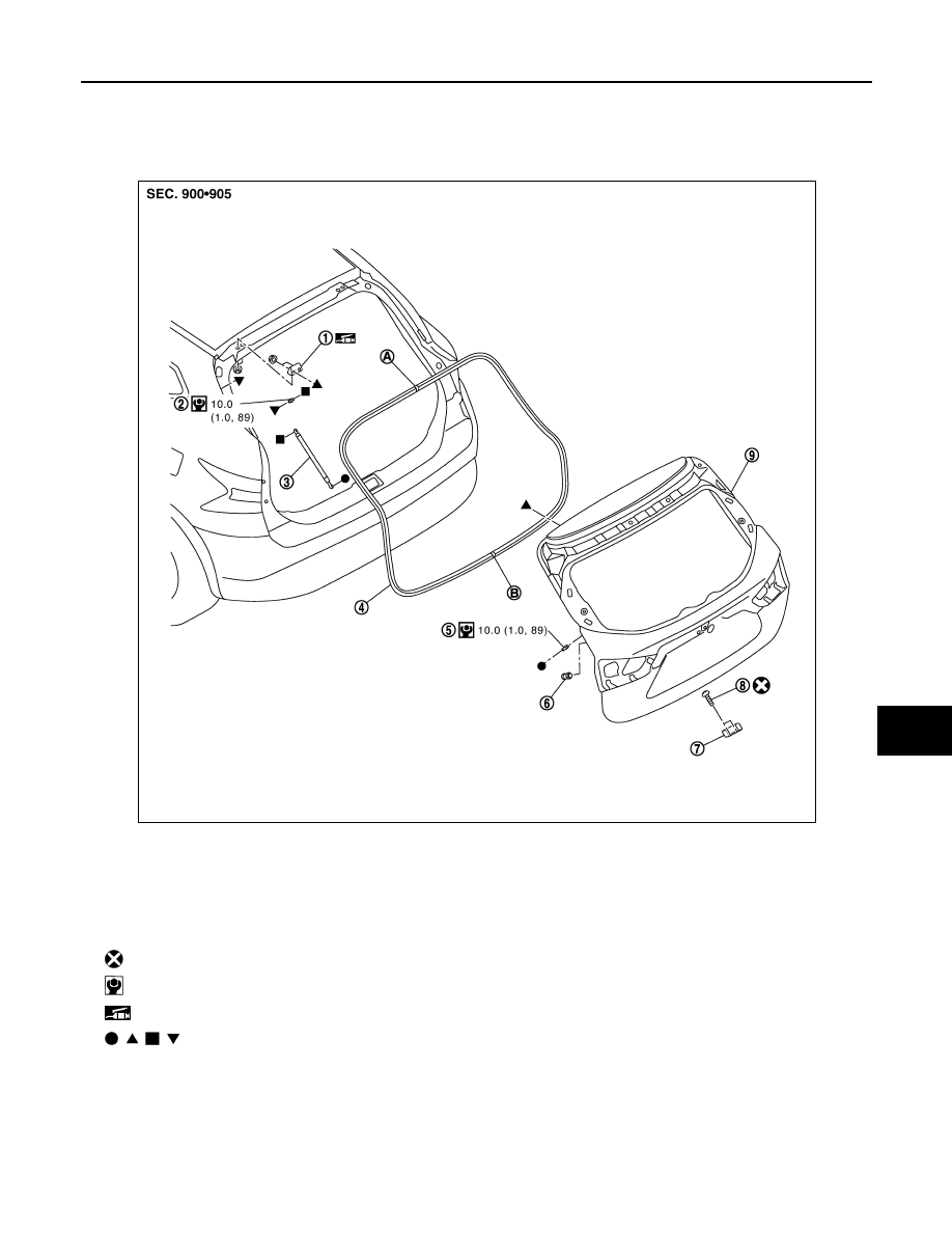
Exploded View
INFOID:0000000010434710
BACK DOOR ASSEMBLY
BACK DOOR ASSEMBLY : Removal and Installation
INFOID:0000000010434711
CAUTION:
• Perform work with 2 workers, because of its heavy weight.
• Use protective tape or shop cloth to protect from damage during removal and installation.
1.
Back door hinge
2.
Stud ball
3.
Back door stay
4.
Back door weather-strip
5.
Stud ball
6.
Back door bumper rubber
7.
Back door striker
8.
TORX bolt
9.
Back door panel
A.
Center mark
B.
Seam
: Always replace after every disassembly.
: N·m (kg-m, in-lb)
: Body grease
,
,
,
: Indicates that the part is connected at points with same symbol in actual vehicle.
JMKIB3637GB