Content .. 1087 1088 1089 1090 ..
Nissan Qashqai J11. Manual - part 1089
HA-182
< REMOVAL AND INSTALLATION >
[TYPE 4]
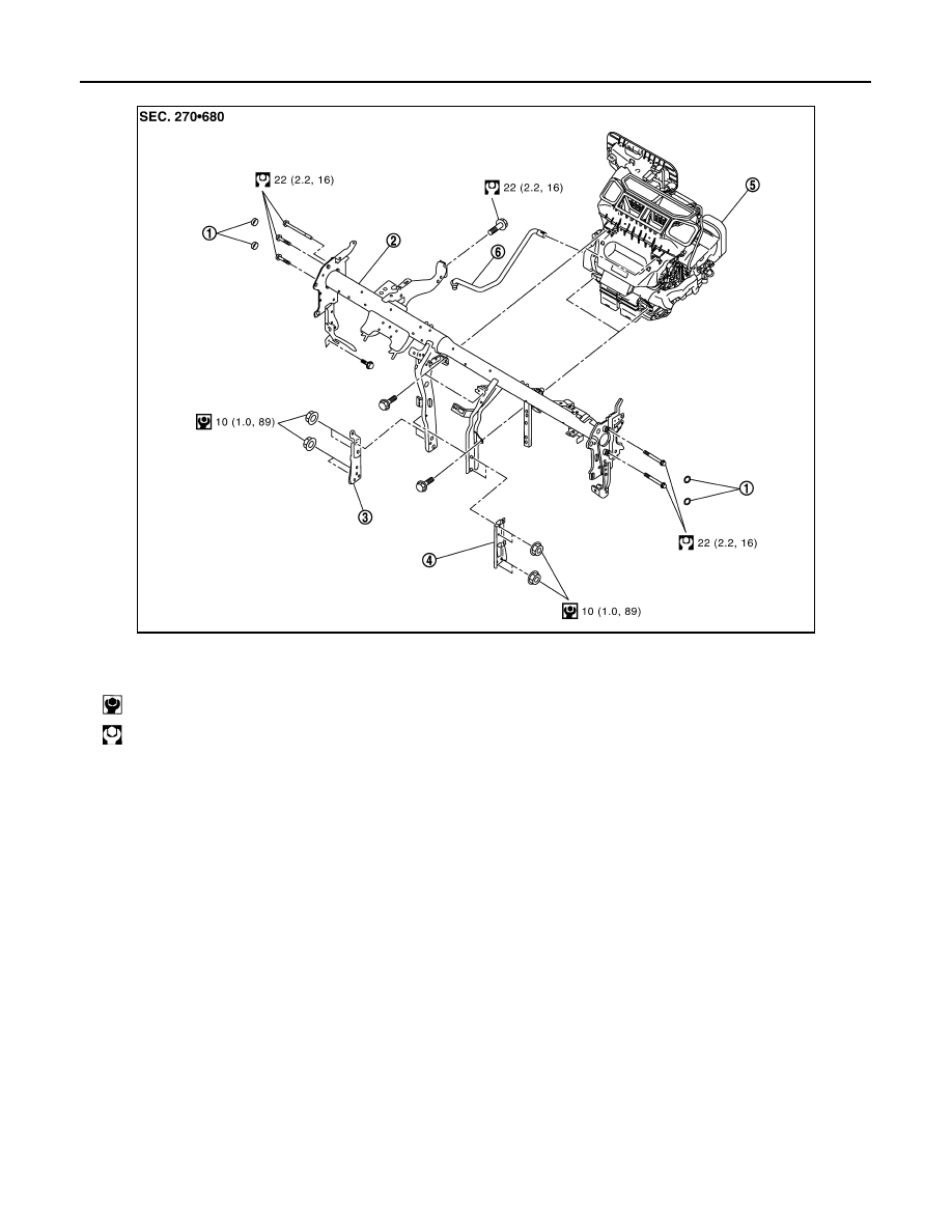
A/C UNIT ASSEMBLY
LHD models
DISASSEMBLY
JMIIA3519GB
1.
Cap
2.
Steering member
3.
Instrument stay LH
4.
Instrument stay RH
5.
A/C unit assembly
6.
Drain hose
: N·m (kg-m, in-lb)
: N·m (kg-m, ft-lb)