Nissan Qashqai J11. Manual - part 96
CYLINDER HEAD
EM-323
< UNIT DISASSEMBLY AND ASSEMBLY >
[K9K]
C
D
E
F
G
H
I
J
K
L
M
A
EM
N
P
O
CYLINDER HEAD
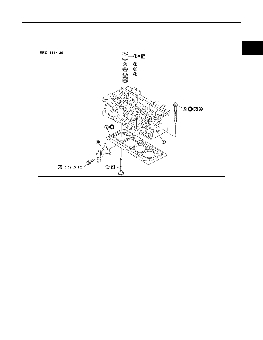
Exploded View
INFOID:0000000010282099
Removal and Installation
INFOID:0000000010282100
REMOVAL
1.
Remove the following parts.
• Engine cover.
• Air inlet tube: Refer to
.
• Rocker cover: Refer to
EM-303, "Removal and Installation"
• Injection tube and fuel injector: Refer to
EM-293, "Removal and Installation"
• High pressure supply pump:
EM-300, "Removal and Installation"
.
• Exhaust manifold: Refer to
EM-289, "Removal and Installation"
• Timing belt: Refer to
EM-305, "Removal and Installation"
.
• Camshaft: Refer to
EM-313, "Removal and Installation"
.
1.
Valve lifter
2.
Valve collet
3.
Valve spring retainer
4.
Valve spring
5.
Cylinder head bolt
6.
Cylinder head
7.
Cylinder head gasket
8.
Engine slinger
9.
Valve
A.
25.0 N·m (2.6 kg-m, 18ft-lb) and 255 degrees
Refer to
E1BIA0024GB