Nissan Qashqai J11. Manual - part 66


  Index      Nissan     Nissan Qashqai J11 - Service and Repair Manual


Search            


Content   ..  64  65  66  67   ..


Nissan Qashqai J11. Manual - part 66


CAMSHAFT

EM-203

< UNIT DISASSEMBLY AND ASSEMBLY >

[MR20DD]

C

D

E

F

G

H

I

J

K

L

M

A

EM

N

P

O

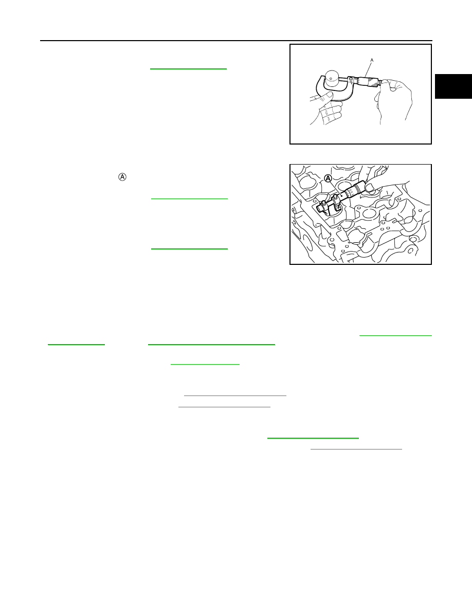
• Measure the outer diameter of valve lifter with a micrometer (A).

VALVE LIFTER HOLE DIAMETER
Measure the inner diameter of valve lifter hole of cylinder head with
an inside micrometer 

.

VALVE LIFTER CLEARANCE
• (Valve lifter clearance) = (Valve lifter hole diameter) – (Valve lifter

outer diameter)

• If out of the standard, referring to the each standard of valve lifter

outer diameter and valve lifter hole diameter, replace either or both
valve lifter and cylinder head.

INSPECTION AFTER INSTALLATION

Inspection of Camshaft Sprocket (INT), (EXH) Oil Groove

CAUTION:

• Perform this inspection only when DTC P0011 or P0014 is detected in self-diagnostic results of CON-

SULT and it is directed according to inspection procedure of EC section. Refer to 

ECM-157, "Diagno-

sis Procedure"

 (P0011) or 

ECM-161, "Diagnosis Procedure"

 (P0014).

• Check when engine is cold so as to prevent burns by the splashing engine oil.
1.

Check engine oil level. Refer to 

LU-22, "Inspection"

.

2.

Perform the following procedure so as to prevent the engine from being unintentionally started while
checking.

a.

Release the fuel pressure. Refer to 

ECM-135, "Work Procedure"

.

b.

Remove intake manifold. Refer to 

EM-149, "Exploded View"

.

c.

Disconnect ignition coil and injector harness connectors.

d.

Support the bottom surface of engine using a transmission jack, and then remove the engine mounting
bracket (RH) and engine mounting insulator (RH). Refer to 

EM-172, "Exploded View"

.

3.

Remove intake or exhaust valve timing control solenoid valve. Refer to 

EM-183, "Exploded View"

.

• Lift the front side of the engine with a jack base to remove intake or exhaust valve timing control sole-

noid valve.

4.

Clean the mounting area of intake or exhaust valve timing control solenoid valve, and then insert a clean
waste with no oil adhesion into the oil hole of the cylinder head.

5.

Install engine mounting insulator (RH) and engine mounting bracket (RH). (After the removal of intake or
exhaust valve timing control solenoid valve and insertion of a waste into the oil hole.)

6.

Perform cranking to check that engine oil comes out from the oil hole (mounting hole of intake or exhaust
valve timing control solenoid valve) of cylinder head.
• Regarding the engine oil check, judge it by the amount of oil adhered to the wasted inserted into the oil

hole.

WARNING:

• Never insert fingers into the oil hole.
• Never touch rotating parts (drive belt, idler pulleys and crankshaft pulley, etc.).

CAUTION:

Standard

: Refer to 

EM-249, "Camshaft"

.

JPBIA0125ZZ

Standard

: Refer to 

EM-249, "Camshaft"

.

Standard

: Refer to 

EM-249, "Camshaft"

.

PBIC3184J

EM-204

< UNIT DISASSEMBLY AND ASSEMBLY >

[MR20DD]

CAMSHAFT

• Never perform cranking without installing the engine mounting insulator (RH) and engine mount-

ing bracket (RH).

• Prevent splashing by using a shop cloth so as to prevent the worker from injury from engine oil

and so as to prevent engine oil contamination.

• Prevent splashing by using a shop cloth so as to prevent engine oil from being splashed to

engine and vehicle. Especially, be careful not to apply engine oil to rubber parts of drive belt,
engine mounting insulator, etc. Wipe engine oil off immediately if it is splashed.

7.

Perform the following inspection if engine oil does not come out from intake or exhaust valve timing con-
trol solenoid valve oil hole of the cylinder head.
• Clean oil groove between oil strainer and intake valve timing control solenoid valve. Refer to 

LU-20,

"Engine Lubrication System"

 and 

LU-21, "Engine Lubrication System Schematic"

.

8.

Remove components between intake or exhaust valve timing control solenoid valve and camshaft
sprocket (INT) or (EXH), and then check each oil groove for clogging.
• Clean oil groove if necessary. Refer to 

LU-20, "Engine Lubrication System"

 and 

LU-21, "Engine Lubrica-

tion System Schematic"

.

9.

After inspection, install removed parts in the reverse order.

OIL SEAL

EM-205

< UNIT DISASSEMBLY AND ASSEMBLY >

[MR20DD]

C

D

E

F

G

H

I

J

K

L

M

A

EM

N

P

O

OIL SEAL

VALVE OIL SEAL

VALVE OIL SEAL : Removal and Installation

INFOID:0000000010715505

REMOVAL

1.

Remove camshafts. Refer to 

EM-196, "Exploded View"

.

2.

Remove valve lifters. Refer to 

EM-196, "Exploded View"

.

3.

Rotate crankshaft, and set piston whose valve oil seal is to be removed to TDC. This will prevent valve
from dropping into cylinder.

CAUTION:

When rotating crankshaft, be careful to avoid scarring front cover with timing chain.

4.

Remove valve collet. 
• Compress valve spring with the valve spring compressor [SST:

KV10116200] (A), the attachment [SST: KV10115900] (C), and
the adapter [SST: KV10109220] (B). Remove valve collet with
magnet hand.

CAUTION:

• Never damage valve lifter holes.
• Fit the attachment [SST: KV10115900] in the center of

valve spring retainer to press it.

5.

Remove valve spring retainer and valve spring (with valve spring seat).

CAUTION:

Never remove valve spring seat from valve spring.

6.

Remove valve oil seal with the valve oil seal puller [SST:
KV10107902] .

INSTALLATION

1.

Apply new engine oil to valve oil seal joint surface and seal lip.

JPBIA1365ZZ

: Valve spring retainer

: Attachment

JPBIA4477ZZ

PBIC3210J

EM-206

< UNIT DISASSEMBLY AND ASSEMBLY >

[MR20DD]

OIL SEAL

2.

Press in valve oil seal to the height (H) shown in the figure with
the valve oil seal drift [SST: KV10115600] 

.

3.

Install in the reverse order of removal, for the rest of parts.

FRONT OIL SEAL

FRONT OIL SEAL : Removal and Installation

INFOID:0000000010715506

REMOVAL

1.

Remove the following parts.
• Front fender protector (RH): Refer to 

EXT-31, "Exploded View"

.

• Drive belt: Refer to 

EM-139, "Exploded View"

.

• Crankshaft pulley: Refer to 

EM-222, "Exploded View"

.

2.

Remove front oil seal with a suitable tool.

CAUTION:

Never damage front cover and crankshaft.

INSTALLATION

1.

Apply new engine oil to new front oil seal joint surface and seal lip.

2.

Install front oil seal so that each seal lip is oriented as shown in
the figure.

• Press-fit front oil seal using a suitable drift with outer diameter 57 mm (2.24 in) and inner diameter 45

mm (1.77 in).

CAUTION:

• Never damage front cover and crankshaft.
• Press-fit oil seal straight to avoid causing burrs or tilting.

3.

Install in the reverse order of removal, for the rest of parts.

REAR OIL SEAL

REAR OIL SEAL : Removal and Installation

INFOID:0000000010715507

REMOVAL

Height (H)

: 15.1 - 15.7 mm (0.594 - 0.618 in)

PBIC3211J

: Dust seal lip

: Oil seal lip

: Engine outside

: Engine inside

PBIC3485J

Within 0.3 mm (0.012 in) toward engine front (crankshaft pulley side)

Within 0.5 mm (0.020 in) toward engine rear (crankshaft sprocket side)


Content   ..  64  65  66  67   ..