Nissan Qashqai J11. Manual - part 57


  Index      Nissan     Nissan Qashqai J11 - Service and Repair Manual


Search            


Content   ..  55  56  57  58   ..


Nissan Qashqai J11. Manual - part 57


FUEL INJECTOR AND FUEL TUBE

EM-167

< REMOVAL AND INSTALLATION >

[MR20DD]

C

D

E

F

G

H

I

J

K

L

M

A

EM

N

P

O

a.

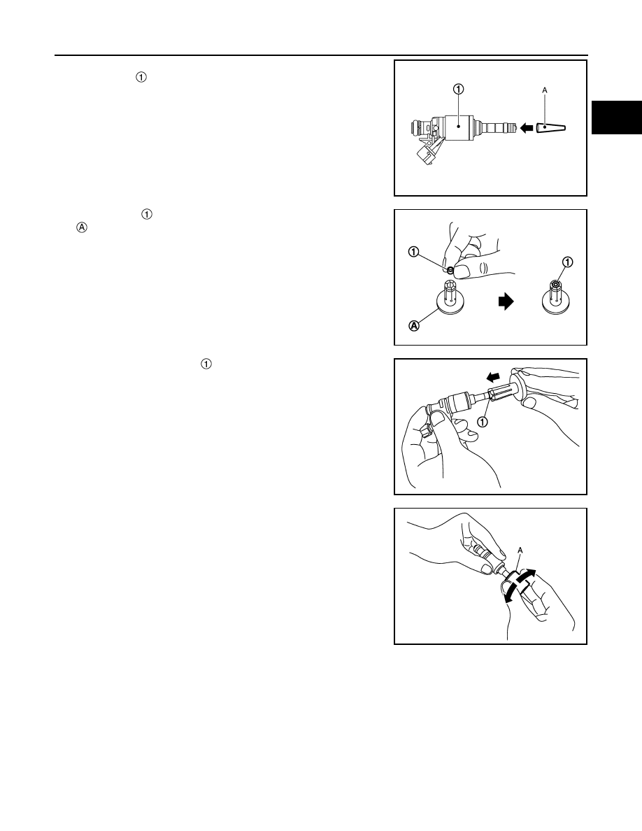
Install an injector seal drift set [SST: KV101197S0 (—)] (A) to
fuel injector 

.

b.

Set seal ring 

 to injector seal drift set [SST: KV101197S0 (—)]

c.

Straightly insert seal ring 

, which is set in step 2, to fuel injec-

tor as shown in the figure and install.

CAUTION:

Be careful that seal ring does not exceed the groove portion
of fuel injector.

d.

Insert injector seal drift set [SST: KV101197S0 (—)] (A) to injec-
tor and rotate clockwise and counterclockwise by 90

°

 while

pressing seal ring to fit it.
NOTE:
Compress seal ring, because this operation is for rectifying
stretch of seal ring caused by installation and for preventing
sticking when inserting injector into cylinder head.

2.

Install O-ring and backup ring to fuel injector. When handing new O-ring and backup ring, paying attention
to the following caution items:

CAUTION:

• Do not reuse O-ring.
• Handle O-ring with bare hands. Never wear gloves.
• Lubricate O-ring with new engine oil.
• Never clean O-ring with solvent.
• Check that O-ring and its mating part are free of foreign material.
• When installing O-ring, be careful not to scratch it with tool or fingernails. Also be careful not to

twist or stretch O-ring. If O-ring was stretched while it was being attached, never insert it quickly
into fuel tube.

JPBIA4386ZZ

JSBIA0348ZZ

JSBIA0350ZZ

JSBIA0351ZZ

EM-168

< REMOVAL AND INSTALLATION >

[MR20DD]

FUEL INJECTOR AND FUEL TUBE

• Insert new O-ring straight into fuel rail. Never decenter or twist it.
• Always install the back up ring 

 in the right direction as

instructed.

3.

Install fuel injector 

 to fuel rail 

 as per the following:

a.

Install fuel injector holder 

 to fuel injector.

CAUTION:

• Never reuse fuel injector holder. Replace it with a new

one.

• Be careful to keep fuel injector holder from interfering

with O-ring. If interference occurs, replace O-ring.

b.

Insert fuel injector into fuel rail with fuel injector holder attached.
• Insert it while matching it to the axial center.
• Insert so that protrusion 

 of fuel injector is aligned to cutout

.

c.

Check that installation is complete by checking that fuel injector
does not rotate or come off.
• Check that protrusions of fuel injectors and fuel rail are aligned

with cutouts of clips after installation.

4.

Install fuel rail and fuel injector assembly to cylinder head.
• Tighten mounting bolts and nuts in two steps in numerical

order as shown in the figure.

5.

Connect injector harness connector.

6.

Install fuel pressure sensor, if removed. 

7.

Install fuel rail insulator.

CAUTION:

• As covering part of fuel tube connector at the back end of common rail can easily move because

of its shape, do not remove it before installation.

• Install the insulator so that it is placed under lower side of intake manifold flange.

8.

Install in the reverse order of removal after this step.

JPBIA3864ZZ

: O-ring (blue)

: Backup ring

JPBIA4387ZZ

: Engine front

 1st step

: 10.0 N·m (1.0 kg-m, 89 in-lb)

 2nd step

: 20.5 N·m (2.1 kg-m, 15 ft-lb)

JPBIA4388ZZ

FUEL INJECTOR AND FUEL TUBE

EM-169

< REMOVAL AND INSTALLATION >

[MR20DD]

C

D

E

F

G

H

I

J

K

L

M

A

EM

N

P

O

Inspection

INFOID:0000000010715486

INSPECTION AFTER INSTALLATION

Check on Fuel Leakage

1.

Turn ignition switch “ON” (with the engine stopped). With fuel pressure applied to fuel piping, check there
are no fuel leakage at connection points.
NOTE:
Use mirrors for checking at points out of clear sight.

2.

Start the engine. With engine speed increased, check again that there are no fuel leakage at connection
points.

CAUTION:

Never touch the engine immediately after stopped, as the engine becomes extremely hot.

EM-170

< REMOVAL AND INSTALLATION >

[MR20DD]

IGNITION COIL, SPARK PLUG AND ROCKER COVER

IGNITION COIL, SPARK PLUG AND ROCKER COVER

Exploded View

INFOID:0000000010715487

Removal and Installation

INFOID:0000000010715488

REMOVAL

1.

Remove intake manifold. Refer to 

EM-149, "Exploded View"

.   

2.

Remove PCV valve and PCV hose, if necessary.

Ignition coil

Spark plug

Rocker cover

Rocker cover gasket

Oil filler cap

PCV valve

O-ring

Comply with the installation proce-
dure when tightening. Refer to 

EM-

170

: Always replace after every disassembly.

: N·m (kg-m, ft-lb)

: N·m (kg-m, in-lb)

JPBIA6815GB


Content   ..  55  56  57  58   ..